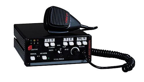
This siren incorporates the popular packaging and features of the original MasterCom siren, plus added features that make it the one that can do it all!
General Specs
- Dimensions: 6.75” L x 2.75” H x 7” W (171.45 mm x 69.85 mm x 177.8 mm)
- Instant-On
- Park Kill – for both lighting & siren
- Adjustable Backlighting
- Brake and Back-Up Light Cut-Off (3940 Series)
- Automatic Short Circuit Protection
- Selectable Hit-N-Go or Horn Ring Scroll Modes
- Siren Lock
- Mounting Bail
Premium Options
- InterClear
- LightAlert
- Mic Jack
- 15 second timed out-put switch
- 200 watt upgrade
- Plug-In Microphone (used with Mic Jack or Common Mic option)
Individual Product Specs
Model 3942 – Full feature 100w Siren w/Hard-wired Microphone, plus Electronic Air Horn, Siren Lock
Model 3942L4 – Same as above, Plus, 3-level slide, 2 Push On/Off, 1 momentary, 1 Brake cut-off, Siren Lock
Model 3942L6 – Same as above, Plus, 3-level slide, 4 Push On/Off, 1 momentary, 1 Brake cut-off, Siren Lock
Model 3892L4 – Same as 3942, plus 4 Standard Push On/Off Button, 3-Level Slide Switch
Model 3892L6 – Same as 3942, plus 6 Standard Push On/Off Button, 3-Level Slide Switch
Model 3944L4 – Same as 3942L4, common mic ready (mic sold separately)
Standard Features:
The enhanced 3890 series sirens consist of integrated controls and amplifier in a single package with 4 and 6 circuit lighting controls available as well. The models are as follows:
3892 – Primary Tones: Wail, Yelp, Hi-Lo, Air Horn
- Secondary Tones: HyperYelp, HyperLo
3892L4,L6 – Primary Tones: Wail, Yelp, Hi-Lo, Air Horn
- Secondary Tones: HyperYelp, HyperLo
- 4 or 6 auxiliary lighting controls
3894L6S – same features as 3892L6 with an addition of a rear panel connector to accommodate a single microphone system.
The following features are standard in the new style 3890 series (tones and sequences may differ by model number):
Instant-On – There is no ” ON/OFF ” switch. Selecting any siren function, or keying the microphone will activate the siren assuming the siren is connected directly to a non ignition switched source of +12V.
SirenLock TM (L4 and L6 Models Only) – An interlock circuit between the siren and the light control circuits that permits automatic siren tones only when the progressive switch is in Level 3 or in Level 2 or 3 (user selectable – works in conjunction with the horn transfer relay). This feature is used in jurisdictions that require warning lights to be on before the siren is activated.
Park Kill – This feature deactivates the siren tones when the vehicle is shifted into park. Once PKILL is activated the siren will remain deactivated until an action occurs such as moving the selector switch to STANDBY, returning lighting level switch to position one or keying the microphone. Any action will enable the siren tones to function again with the exception of the auxiliary lighting push buttons. On lighting models this also drops-out the Level 3 lighting output for a power- down mode when in park.
Adjustable Backlighting – Backlighting is independent of siren power. Allows connecting to dimmer if desired.
Radio Power – Allows user to power the two-way radio from the siren when the ignition is “OFF”.
Automatic Short Circuit Protection – The siren will sense a short circuit on the speaker terminals and automatically go to standby until the fault is removed. Once the fault is removed the siren will return to normal operation.
Lighting Level “3 ” Drop-out – When vehicle is shifted to PARK and the PKILL feature is connected, Level 3 lighting will drop-out. This is indicated by the “red” LED extinguishing. This is a power down mode and can be defeated by setting the 4 -position rear dip switch to the PKILL “OFF” position on the lighting board.
Scroll Mode – Setting the slide switch on the rear of the siren to the SCROLL position will put siren in scroll mode. This will allow “scrolling” through tones utilizing sharp taps on the horn ring, or a switch, via the Remote siren input. In this mode holding the horn ring for prolonged durations will produce the Airhorn sound. See OPERATION section for further details.
Hit-n-Go Mode – Setting the slide switch on the rear of the siren to the Hit-N-Go position will put the siren in the Hit-n-Go mode. This mode will be most familiar to existing Mastercom users. A seven second override is standard for all tones when activated by the Manual button or the Remote input. See OPERATION section for details.
Automatic Siren Tones – Industry standard Wail, Yelp, and Hi-Lo tones.
AIR HORN Tone – Electronic AIR HORN sound.
Instant Public Address – Public Address override of all siren functions when the microphone Push-to-Talk key is pressed.
Status LED – An indicator LED, visible on the front panel that informs the operator of the status of his siren at all times.
Radio Rebroadcast – Broadcast Two-way radio reception over siren speakers. These inputs are transformer coupled to prevent loading of the radio.
Remote Siren Switching – The siren accepts either a positive or a ground (earth) signal, usually from the vehicle’s horn switch (or other user supplied switch), and remotely activates the MANUAL or AIR HORN (if supplied) function. Selection is made via the front panel slide switch. The siren is factory set for a GND
(Earth) signal and may be reconfigured to accept a positive signal. See Set-up and Adjustments section for details.
Tone Priority/Manual Wail – The following tones are produced while pushing the MANUAL Push-button or triggering the user-supplied REMOTE siren switch:
Manual Wail when the MANUAL Push-button is depressed while the rotary switch is in the STANDBY position.
Yelp when the MANUAL Push-button is depressed while the rotary switch is in the WAIL position.
HyperYelp when the MANUAL Push-button is depressed and the rotary switch is in the YELP position.
HyperLo when the MANUAL Push-button is depressed and the rotary switch is in the HI-LO position.
Noise Cancelling Microphone – Wired in microphone that is easily unplugged internally for service or replacement.
Power Distribution Section – A three level progressive switch for primary warning light system control plus 4 push on/push-off auxiliary switches that are user convertible to momentary action (‘L4 models). The unit may also be purchased with 6 auxiliary switches (‘L6 models).
Each auxiliary switch can be custom labeled with the supplied label kit. Each label is backlit and increases intensity when activated to alert the operator. Each position of the progressive switch has its own indicator LED.
Horn Ring Transfer – (‘L models only) Built in horn transfer relay that may be activated at Levels 2 and 3 of the warning light progressive switch. Point of activation is customer selectable with the rear panel DIP switch.
Amplifier Connections
Siren Amplifier Connector – As a standard feature, the Siren and Auxiliary sections (‘L4 & ‘L6 models) of your unit come equipped with a combination plug-in terminal block/connector. To terminate the wires, strip approximately 1/4″ of insulation from the end of each wire and insert it in the appropriate hole in the terminal block. Recommend using a screwdriver with a 1/8″ wide blade with a 6″ shaft such as an Xcelite(C) R186 or equivalent rather than a 4 1/2″ adjustment screwdriver to ensure proper torque on the screws. Tighten the set-screw and proceed to the next connection.
Should you ever have to remove the unit, pull the terminal block straight out. It will unplug from the unit, leaving the wiring in place.
Terminal Block Connections
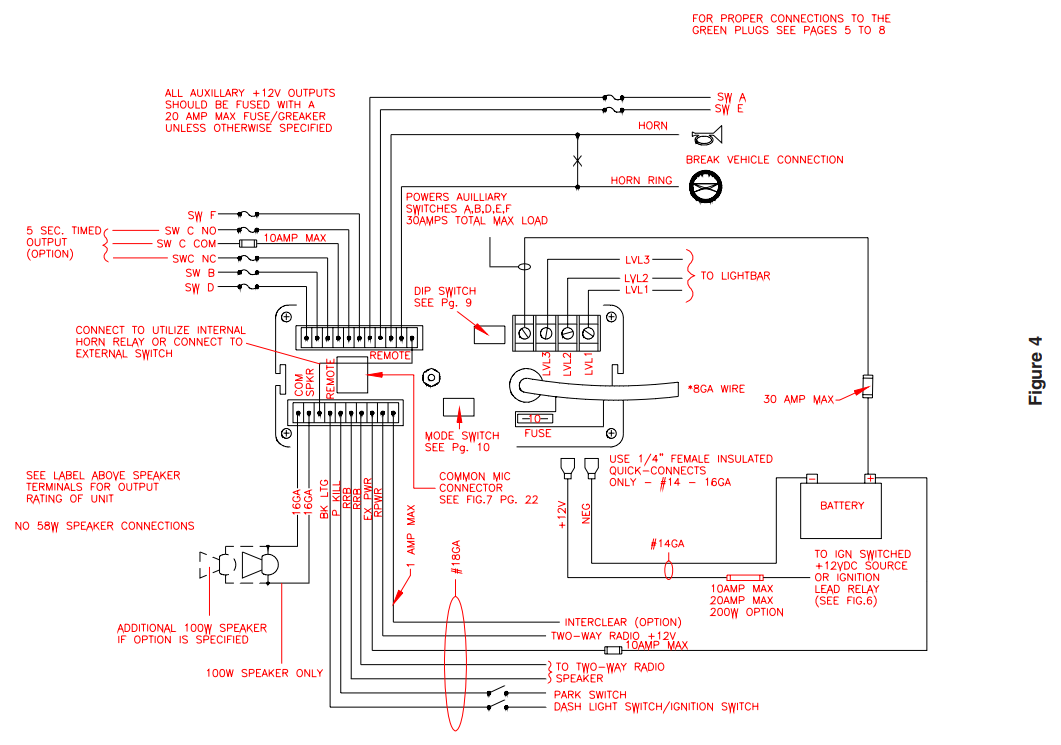
10 Position Terminal Plug – ( see wiring diagram )
COM – Connect to the terminal marked “1” of one 100 W ( 11 ohm ) speaker.
SPKR – Connect to the terminal marked “2” of the 100 W ( 11 ohm ) speaker.
NOTE: An optional 200 W version is available. This will enable the user to connect two 100 W speakers in parallel. Correct phasing is important and can be accomplished by connecting both speaker terminals marked ” 1 ” to the COM terminal and both speaker terminals marked ” 2″ to the SPKR terminal.
REMOTE – Remote switch (Horn ring or foot switch). Circuit can be configured for both ground (earth) or positive signals. A horn ring transfer circuit is standard in all 3940 series “L” models.
Connect to the “REMOTE” terminal on the Lighting Control Section terminal block. Unit is configured for a ground ( earth ) at the factory. See the details on configuring for a +12V input.
BLTG – Provides +12V to siren backlighting. Connect to a vehicle circuit that is powered when the ignition switch is ” on “. If backlighting dimming is desired, connect to the dash lights’ circuit.
Caution – If connected to the battery the backlighting will be active at all times.
PKILL – This feature automatically deactivates siren tones when the vehicle is shifted into PARK. On models with lighting control Level 3 will ” drop-out ” if this feature is enabled via the rear panel dip switch. Siren tones will be disabled until the vehicle is shifted out of PARK and the front panel selector switched is either returned to standby ( or another function is selected ) or the lighting level control is returned to level 1.
This circuit is activated by a negative signal. Connect this input to a circuit that is GROUNDED (Earth) when the vehicle is shifted into PARK. It is the installer’s responsibility to determine an appropriate location in the vehicle circuitry to connect this wire.
RRB – Connect to one side of the two-way radio speaker.
RRB – Connect to the second side of the two-way radio speaker.
EXPWR – Connect directly to +12V terminal of the battery or a non-ignition switched source of +12V capable of supplying a minimum of 10 Amps.
RPWR – Provides +12V to the two-way radio with the ignition on / off . Connect the +12V power lead from the radio to this terminal. This is a 10 Amp maximum current output.
InterClear® (Optional) – Connect to the device or circuit that is to be activated by the InterClear feature. The InterClear circuit is internally current limited at 1 Amp. Should your requirements require higher currents, use the InterClear Power Booster Kit (# INTBS), available from your Code 3 supplier.
1/4″ Male Quick-Connect Printed Circuit Board Terminals
+12V – Connect to a positive +12 volt DC source. It is recommended that the user protect this wire with a 10 Amp fuse(20 Amp for 200w option) or circuit breaker located at the source. Use #14 gauge wire terminated with 1/4″ female, fully insulated quick-connect terminals only.
NEG – Connect to the negative terminal of the battery. This supplies ground (earth) to the siren. Use #14 gauge wire terminated with 1/4″ female, fully insulated quick-connect terminals only.
Power Distribution Connections ( “L” Models)
A #8 stud is provided on the rear of the unit and is intended for use ONLY as a convenient ground (earth) ” tie-point ” for the light bar wiring. It is not an adequate ground (earth) for the siren or the light bar. It is recommended all ground (earth) wires attached here be terminated with a crimp-on ring terminal.
11-Position Terminal Plug – Rear Panel – ( Wiring Diagram )
IMPORTANT!
Remember auxiliary outputs A,B,D on L4 models and A,B,D,E,F on L6 models can supply a maximum of 20 Amps each for a combined total of 30 Amps. Install appropriate fuses in each output wire as close to the siren as possible.
SW D – Connect to the load to be controlled by Auxiliary Switch “D”.
SW B – Connect to the load to be controlled by Auxiliary Switch “B”.
SW C NO – Connect to the load to be controlled by the normally-open contact on Auxiliary Switch “C”.
SW C NC – Connect to the load to be controlled by the normally-closed contact on Auxiliary Switch “C”.
SW C COM – Common or power feed for Auxiliary Switch “C”. Terminals are a SPDT circuit that may be connected as a momentary (or timed momentary with option) ignition controlled circuit, or used for switching auxiliary circuits. It will Handle 10 Amps, and should be protected with a fuse at the battery if individually fed. Can also be connected to a ground source if the load on SWC NO or SWC NC is already connected to a 12V source and needs a ground input to activate it.
SW F – (‘L6 models only) Connect to the load to be controlled by Auxiliary Switch “F”.
SW A – Connect to the load to be controlled by Auxiliary Switch “A”.
SW E – (‘L6 models only) Connect to the load to be controlled by Auxiliary Switch “E”.
HORN RING – Connect to the wire coming from the vehicle horn switch at the steering wheel.
HORN – Connect to the vehicle horn or vehicle horn ring relay.
REMOTE – Connect to the Remote terminal on the Siren Amplifier Connector.
Lighting Models Only ( L versions )
#8 GAUGE RED WIRE PIGTAIL – provides power to the 3 Level, progressive lighting outputs only. The wire can be ordered with an optional connector to allow for convenient removal. The connector should be soldered to each wire, NOT crimped. This connection is designed to provide 50 amp service and therefore nothing smaller than #8 gauge wire should be connected to it. The circuit breaker used should be sized for the actual load of the lighting used and located as close to the battery positive as possible. For quick disconnection option on 8 AWG wire see “lighting switch connector”.
4 Position Screw-type Terminal Block Connector
Important!
The total combined current for the auxiliary outputs A,B,D on L4 models and A,B,D,E,F on L6 models must not exceed 30 Amps total.
+12VAUX – Connect to the positive terminal of the battery with 30 Amp circuit protection. Locate the fuse or circuit breaker at the battery and use #10 gauge wire minimum. This terminal powers switches A,B and D on L4 models and A,B,D,E and F on L6 models, and also supplied power to the siren lock & light alert circuits on both models.
LEVEL 1 – Connect to the first level of warning lights (Green LED) position “1” on level switch.
LEVEL 2 – Connect to the second level of warning lights (Yellow LED) position “2” on level switch.
LEVEL 3 – Connect to the third level of warning lights (Red LED) position “3” on level switch.
NOTE: LEVEL 1, LEVEL 2, LEVEL 3, switch progressively. Switch position 1 provides +12 volts at Level 1 terminal. Switch position 2 provides +12 volts at terminals 1 and 2. Switch position 3 provides +12 volts at terminals 1, 2, and 3.
SET-UP AND ADJUSTMENT
All of the adjustments, except MAXIMUM P.A. ADJUSTMENT, and set-up switches are accessible from the rear of the unit. Make these adjustments and position the set-up switches prior to placing the unit inside their bail bracket (see wiring diagram ).
Audio Adjustments
Radio Rebroadcast Adjustment – Place the selector switch in the RADIO position. The trimmer located on the rear panel of the siren sets the maximum level RRB will reach with the knob fully clockwise. To adjust properly, set the volume knob fully clockwise and adjust the trimmer such that normal two-way radio volume inside the vehicle produces the desired volume outside the vehicle.
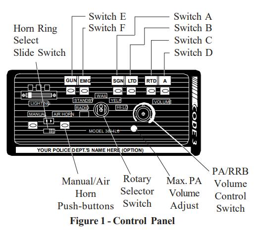
Maximum P.A. Volume Adjustment – This trimmer ( located on the front panel next to the volume control knob ) sets the maximum level that the P.A. volume will reach with the front panel VOLUME control in the fully clockwise position. To adjust properly, set the front panel volume control fully clockwise and adjust the trimmer while keying the microphone until the maximum volume out of the speaker is such that there is no feedback and is intelligible. (See Figure 1)
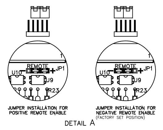
Remote Input: The remote input can be configured to accept either a positive +12V or negative GND ( Earth ) signal for actuation. All new style 3890 series sirens are shipped set-up to accept the GND (Earth) signal from the vehicle HORN SW present on most vehicles. To reconfigure this as a +12V signal the rear
plate must be removed ( see assembly explosion page 19 ). Place both jumpers towards the “+ ” position. Refer to Detail “A” shown above for a complete illustration.
4-Position DIP Switch: Gently set the SirenLock, PKILL and LightAlert set-up switches to the desired position with a pencil point or some other pointed object. These switches are present even if LightAlert were not specified. If switched on, all of the tones except AIR HORN, mute until the Warning Light Switch is in either the Level 3 or the Level 2 or 3 positions.
SirenLock – In position “3” the siren tones are allowed to sound and the horn ring relay transfers when the Warning Light switch is placed in the Level “3” position. In position “2,3” the siren tones are allowed to sound and the horn ring relay transfers when the Warning Light switch is placed in either Level 2 or in Level 3 position.
LightAlert – When in the ON position, enables the LightAlert tone, which alerts the operator audibly when any lighting switch is activated. When in the OFF position, defeats the LightAlert tone.
PKILL – When vehicle is shifted to PARK lighting level 3 will ” drop-out ” if this switch is in the “on “position. This is intended to reduce power consumption while vehicle is not moving. If it is not desired to have level 3 “drop-out” this switch should be set to the ” OFF ” position on the dip switch. This will not defeat the PKILL feature on the siren, but will defeat the level 3 DROP out.
Siren Mode Selector Slide Switch: The siren has two distinct modes, Hit-N-Go and Scroll. Set rear panel slide switch to the desired mode by sliding left or right. See operation section for detailed operation in each mode.
Push-Button Conversion

(‘L models only)
Switches A-F can be set up as momentary (only on while pushed), or push-on/push-off. They can be converted as follows:
1. Disconnect all connectors and wiring to unit. Remove siren from the vehicle if it is installed.
2. Remove the screw holding the rear cover plate to the siren tray.
3. Remove the (4) screws holding the bezel to the extrusion.
4. Slide the front panel/tray assembly forward out of the extrusion.
5. Grasp the rear edge of the Power Distribution Circuit Board (on top), slide it back and lift it free from the (4) standoff fasteners holding it to the lower circuit board. Caution: The circuit board is still attached. See steps 6 & 7 below.
6. Note the orientation of the circuit board four-pin connector and remove.
7. Do the same with the lighting level switch four-pin connector.
8. See Figure 3 for information on converting the switch. Once converted the switch may be converted back again if the toggle pin is not lost.
9. Re-assemble the siren in the reverse order. Note correct orientation of the four and three-pin harness connectors.
Operation
IMPORTANT !
The Mastercom Series has two distinct modes of operation. These are the Hit-N-Go mode and the SCROLL mode. The desired mode of operation can be selected via the rear panel slide switch. Each mode will effect the siren operation as described below. The Hit-N-Go mode should be most familiar to existing Mastercom users.
The siren tones will be deactivated when the vehicle is in “PARK” if the PKILL feature has been connected. To test the siren tones the vehicle must not be in “PARK”. The following assumes that PKILL has not been activated.
Switch Operation – Hit-N-Go Mode Selected Function Selector Switch (Center Knob)
RADIO – In the RADIO position, the audio from the 2-way radio is rebroadcast over the siren speaker. The siren tones (Wail, Yelp, & Hi-Lo) do not operate in this position. In addition, power is routed to the two-way radio via the RPWR pin on the rear panel connector. The EXPWR pin must be wired to the battery positive, and the two-way radio power connected to the RPWR pin.
STANDBY – This is the standby mode. If the MANUAL button is depressed , and the vehicle is not in PARK, the Manual wail tone will ramp up until it reaches a peak then ramp down when released. If the AIR HORN button is depressed, the Air Horn sound will be produced.
WAIL – This position produces the Wail tone. Depressing the MANUAL button or activating the remote input will now produce the Yelp tone for 7 seconds. Depressing the AIR HORN button will produce the Air Horn sound and when released will return siren to Wail tone.
YELP – This position produces the Yelp tone. Pushing the MANUAL button or activating the remote input will now produce the HyperYelp tone for 7 seconds. If the AIRHORN button is pushed, the Airhorn sound will be produced and when released will return the siren to Yelp.
HI-LO – This position produces the Hi-Lo tone. Pushing the MANUAL button or activating the remote input will now produce the HyperLo tone for 7 seconds. If the AIRHORN button is pushed, the Airhorn sound will be produced and when released will return siren to Hi-Lo.
Push-to-Talk (PTT) Microphone Switch – Keying the microphone will automatically override whatever mode the siren is in and broadcast public address messages over the siren speaker. PTT operates in all positions of the Selector switch.
MANUAL Pushbutton Momentary Switch – Has no effect when the selector switch is in RADIO, produces the effects described above for each selector position.
AIR HORN Pushbutton Momentary Switch – Produces the Air Horn tone in all selector switch settings except RADIO.
SLIDE SWITCH – The slide switch located between the AIR HORN and MANUAL buttons selects the function for the REMOTE (external switch) circuitry. When the switch is to the right, the Horn Ring circuitry remotely “depresses” the AIR HORN button and it produces the effects outlined above. When the
slide switch is to the left, it allows the REMOTE circuitry to remotely “depress” the MANUAL pushbutton. This causes the effects described above to occur.
Switch Operation – Scroll Mode Selected
The ” Scroll ” mode is designed to allow the user to scroll through all the tones including Airhorn by utilizing the Remote input on the siren. This will usually be connected to the vehicle Horn Ring circuit. When the siren selector switch is placed in either Wail or Yelp ( and Horn Ring transfer has occurred ) the user can
use the Horn Ring to sequence through Wail, Hyperyelp and Yelp by applying a quick, sharp tap on the horn.
Additional taps will scroll the siren to the next tone. Depressing the horn ring for longer periods will produce ” Airhorn”. After releasing the vehicle’s horn ring, the siren will return to the selected tone.
Function Selector Switch (Center Knob)
RADIO – In the RADIO position, the audio from the 2-way radio is rebroadcast over the siren speaker. The siren tones (Wail, Yelp, & Hi-Lo) do not operate in this position. In addition, power is routed to the two-way radio via the RPWR pin on the rear panel connector. The EXPWR pin must be wired to the battery positive, and the two-way radio power connected to the RPWR pin.
STANDBY – This is the standby mode. If the MANUAL button is depressed the Manual wail tone will ramp up until it reaches a peak then ramp down when released. If the AIR HORN button is depressed, the Air Horn sound will be produced. The siren cannot be scrolled in this position.
WAIL – This position produces the Wail tone. Depressing the MANUAL button will now produce Manual wail tone and ramp up until released. Depressing the AIR HORN button will produce the Air Horn sound. The siren can be scrolled in this position as described above.
YELP – This position produces the Yelp tone. Pushing the MANUAL button will now produce the Manual wail tone and ramp up until released. If the AIRHORN button is pushed, the Airhorn sound will be produced. The siren can be scrolled from this position as described above.
HI-LO – This position produces the Hi-Lo tone. Pushing the MANUAL button will now produce the HyperLo tone for 7 seconds. If the AIRHORN button is pushed, the Airhorn sound will be produced and when released will return siren to Hi-Lo.The siren cannot be scrolled from this position.
Push-to-Talk (PTT) Microphone Switch – Keying the microphone will automatically override whatever
mode the siren is in and broadcast public address messages over the siren speaker. PTT operates in all
positions of the Selector switch.
MANUAL Pushbutton Momentary Switch – Has no effect when the selector switch is in RADIO, produces the effects described above for each selector position.
AIR HORN Pushbutton Momentary Switch – Produces the Air Horn tone in all selector switch settings except RADIO.
SLIDE SWITCH – The slide switch located between the AIR HORN and MANUAL buttons selects the function for the REMOTE (external switch) circuitry. When in the “Scroll ” mode this switch has no effect unless in STANDBY or the Hi-Lo position. When this is the case the switch functions as follows:
When the switch is to the right, the Horn Ring circuitry remotely “depresses” the AIR HORN button and it produces the effects outlined above. When the slide switch is to the left, it allows the REMOTE circuitry to remotely “depress” the MANUAL pushbutton. This causes the effects described above to occur.
LED STATUS INDICATOR – The green LED status indicator indicates the siren is on when lighted. The LED will remain off unless a siren tone or air horn or PA or radio output is selected.
For ‘L4 & ‘L6 Models Only
WARNING LIGHTS 3 LEVEL PROGRESSIVE SLIDE SWITCH:
POSITION 1 – Supplies power to Lighting Level 1, illuminates Green LED and activates LightAlert if supplied.
POSITON 2 – Supplies power to Lighting Levels 1 & 2. illuminates Green & Yellow LED’s and activates LightAlert and SirenLock options if supplied.
POSITION 3 – Supplies power to Lighting Levels 1,2, & 3. Illuminates Green, Yellow, and Red LED’s; and activates LightAlert and SirenLock if supplied.
Auxiliary Switches:
AUXILIARY SWITCH “A” – Supplies power to the load connected to terminal SW A.
AUXILIARY SWITCH “B” – Supplies power to the load connected to terminal SW B.
AUXILIARY SWITCH “C” – Operates circuit connected to terminals SWC NO, SWC NC, SWC COM. Optional functions a momentary activation or a 5 sec. timed switch.
AUXILIARY SWITCH “D” – Supplies power to the load connected to terminal SW D.
For ‘L6 Models Only
AUXILIARY SWITCH “E” – Supplies power to the load connected to terminal SW E.
AUXILIARY SWITCH “F” – Supplies power to the load connected to terminal SW F.
NOTE: All switches have their own individual LED indicating that the circuit is On. All switches will activate the LightAlert feature if it is supplied.
LightAlert – The LightAlert option will produce an audible “beep” on a periodic basis if the Warning Light Switch or any of the Auxiliary Switches are on. A rear accessible circuit board mounted DIP switch is provided to defeat this option.
SirenLock – The SirenLock, when not defeated by means of a rear panel accessible switch, allows siren tones (Wail, Yelp, and Hi-Lo) to be produced only when the Warning Light Switch is in the Lighting Level 2 (Green and Yellow LED’s) or Lighting Level 3 (Green, Yellow, and Red LED’s) position (switch selectable via a rear panel accessible switch). Air Horn, Radio Rebroadcast, and Public Address are unaffected by this option.
Options
Lighting Switch Connector – Connectors which when soldered to the #8 wire and the user supplied power wire offers quick disconnect service.
200W Speaker Output – An optional 200 watt version is available. This enables the user to connect two 100w speakers in parallel.
No HI-Low Siren Tones – “wail” and “yelp” tones are in some cases (such as in the state of California) the only recognized siren tones for calling for the right of way.
Instant Yelp – This product is provided with an INSTANT YELP feature which allows the user to select the YELP tone instantly by depressing the vehicles’ horn switch.
Remote MIC Jack – A plug-in microphone jack in lieu of the standard wired-in microphone may be specified. A plug-in noise-canceling microphone (p/n T07309) must be ordered separately if needed.
LightAlert TM (L4 and L6 Models Only)- An audible alarm pulse that indicates that either the primary warning system or one of the auxiliary control circuits is on. User defeatable.
InterClear® This unique feature can be used to activate additional warning lights for 7 seconds when in an Hit-N-Go override or ” scrolling ” by pushing a single button or the vehicle horn ring, thus allowing an additional level of warning in situations such as intersections without the operator having to take his hands off the wheel or his eyes off the road.
InterClear Booster Kit (part# ntbs) Increases interclear option’s output capability for loads greater than 1 amp.
Custom Engraving (CUSENG) – The lower portion of the faceplate can be engraved with department name or other information.
Air Horn only – This option disables the primary and secondary siren tones while still enabling the Air horn tone, Radio Rebroadcast and PA outputs. The primary warning and auxiliary lighting controls remain unaffected.
Specifications
Siren Section
- Input Voltage – 10 to 16 VDC, negative ground (earth). (Note: Operation above 15 VDC for an extended period of time may result in speaker damage.)
- Operating Current: 8 Amps @ 13.6V with 11-ohm load ( 100 W Spkr )
- For optional 200 Watt operation: 14 Amps @ 13.6V with 5.5-ohm load ( 2- 100 W Spkr )
- Note: There is no 58 Watt speaker connection available.
- Standby Current: 12 mA excluding backlighting
- Cycle Rate: WAIL – 11 cycles/minute. YELP – 200 cycles/minute.
- Voltage Output ( approx. ) 64 V peak-to-peak
Audio Section
- Audio Response: 3 dB down points – 500 to 3000 hz.
- 1000 hz. 0 dB Reference
- Audio Distortion: 10% or less below clipping.
Lighting Section (“L” Models Only)
Warning Light Control:
- Progressive switching, 3 levels
- 50 Amps. maximum combined total to #8 wire
- Audible alarm (optional)
Level 1 30A maximum / Green LED Indication
Level 2 30A maximum / Yellow LED Indication
Level 3 30A maximum / Red LED indication.
Auxiliary Control – SPST ( Aux. Switches A, B,C,D,E, F )
- Accessory Switch operation – Push-on/off convertible to momentary operation.
- Independent circuits – 4 (‘L4), 6 (‘L6).
- 30 Amps. maximum combined total 20 Amps. maximum load for any single output A,B,C,D,E or F
- Green LED indication
- Audible alarm (optional)
Horn Transfer Relay – SPDT:
- Activated in Level 2 or Levels 2 & 3 (User selectable)
- 10 Amps. maximum connected load
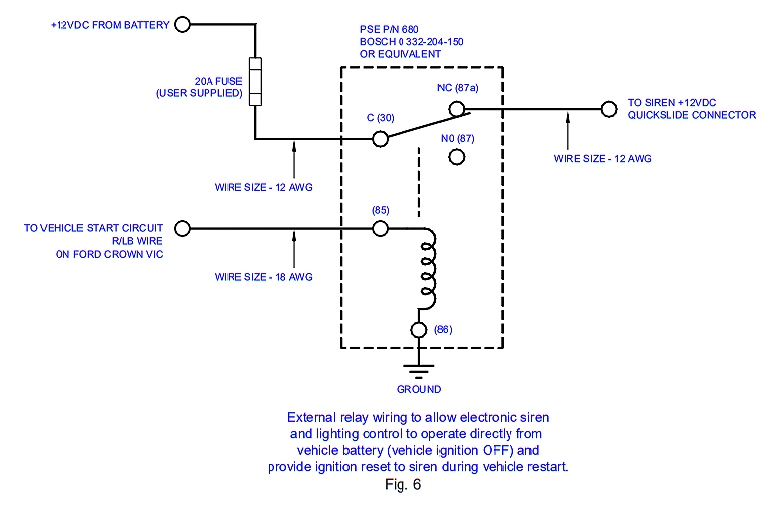
External Ignition Lead Relay for 3890 Series Siren Systems
DESCRIPTION:
Normal installation procedure requires the siren’s +12VDC power connection to be connected to the vehicle’s ignition circuit so that the ignition key must be in the on position for the system to operate. In cases where vehicle security is a consideration it may be desirable to connect the siren system directly to the vehicle’s battery in order to allow the siren and lighting control to be operated with the vehicle’s ignition switch in the off position. This requires that the siren’s +12VDC power connection be routed through the normally closed (NC) contacts of a SPDT relay (user supplied). This is easily accomplished using the wiring method described below.
OPERATION:
Refer to the appropriate user instruction manual for details on the configuration and operation of the MasterCOM Siren System.
WIRING:
The basic connections are shown in Fig. 1 below. Please note that other equivalent relays and vehicles of different makes and models may require slightly different connections. Mount and wire the siren amplifier in compliance with the instructions in the user manual. Read and comply with all safety warnings. Refer to the vehicle manufacturer’s wiring diagram to determine the location and wire color of the start circuit. Securely mount the external relay. Use the appropriate wire size as indicated in Fig. 1, and insure that all wiring is properly terminated and secured in a manner that does not interfere with other systems within the vehicle.
Code 3 MasterCom Siren Tones
Air Horn
Wail
Yelp
Hyper Yelp
Hi-Lo
Hyper Lo
Manuals & Ads:
Code 3 MasterCom Installation & Operation Manual
Video:
About The Author
Code 3 Garage
I started my career as a police officer in 1989 with the Geneva on The Lake Police Department. I worked part time as a police officer and full time as a Security Sergeant doing armed mobile security patrols for a local security company. In 1990 I became a State Trooper with the Ohio State Highway Patrol. During my career as a State Trooper I was certified as a Technical Crash Investigator, OPOTA Police Instructor, OPOTA Police Driving Instructor, LASER Instructor, and received awards for ACE (Auto Larceny) and Post Trooper of The Year. Code 3 Garage is a mix of my inner automotive gearhead, and public safety background. I hope you enjoy it!