Introduction
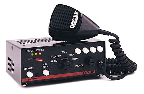
Code 3 Inc.’s electronic sirens are compact, easy to use, and reliable. They’re also energy-efficient, with solid-state technology that offers the best combination of features and value in the industry.
The V-Con Siren is available with or without Electronic Air Horn, with Wail, YeIp and either HiLo or HyperYelp™ siren tones, plus Public Address and Radio Rebroadcast.
Light control models have built-in relays and seven levels of control, with a 3-level progressive switch and four push-on/push-off auxiliary switches. Hit-N-Go is standard.
They may be ordered with common microphone capability for use with the 2-way radio microphone, or with their own wired-in microphone. All models are back-lit for easy night operation.
General Specs
- Dimensions: 6.5” L x 2.5” H x 5.5” W (165.1 mm x 63.5 mm x 139.7 mm)
- Electronic Air Horn
- Wail, Yelp
- Hi-Lo or HyperYelp™
- Public Address
- Radio Rebroadcast.
- Hard-wired microphone.
- Backlighting for easy night operation
- 200 watt
Premium Options
- InterClear
- LightAlert
- Mic Jack
- Siren Lock
- Plug-In Microphone (used with Mic Jack option)
Standard Features
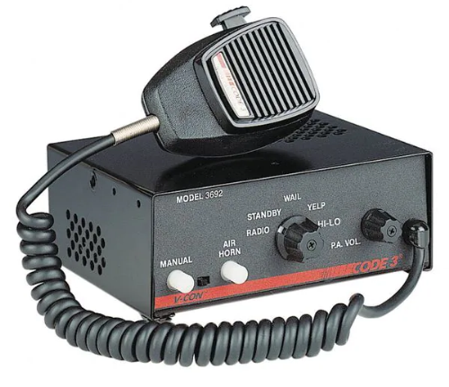
The 3690 series sirens consist of integrated controls and amplifier in a single package with 7 circuit lighting controls available as well. The models are as follows:
3672 – Primary Tones: Wail, Yelp, HyperYelp, Air Horn
- Secondary Tones: HyperYelp, Yelp
3692 – Primary Tones: Wail, Yelp, Hi-Lo, Air Horn
- Secondary Tones: Yelp
3696P – Air Horn, PA & Radio Rebroadcast only
3622 – Same as 3692 but 24 Volt rated
3672L4 – Same as 3672 plus Light Controls
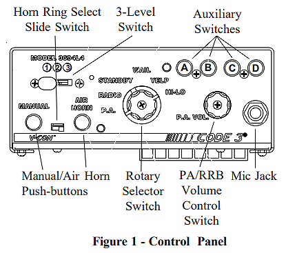
3692L4 – Same as 3692 plus Light Controls
3696PL – Same as 3696P plus Light Controls
3694– Same features as 3692 with addition of a rear panel connector to accommodate single microphone systems
3694L4 – Same as 3694 model plus Lighting Controls The following features are standard in the 3690 series (tones and sequences may differ by model number):
Automatic Short Circuit Protection – The siren will sense a short circuit on the speaker terminals and automatically go to standby until the fault is removed. Once the fault is removed the siren will return to normal operation.
Hit-n-Go Mode – Setting the slide switch (DETAIL B, 4) inside, on the V-CON amplifier board toward the front panel will put the siren in the Hit-n-Go mode. This mode will be most familiar to existing V-CON users. A seven second override is standard for all tones when activated by the Manual button or the Remote input.
Siren Tones – Industry standard Wail, Yelp, and Hi-Lo tones.
AIR HORN Tone – Electronic AIR HORN sound.
Public Address – Public Address override of all siren functions when the microphone Push-to-Talk key is pressed.
Auxiliary Switch, Status LED – An indicator LED, visible on the front panel that informs the operator of the status of the A,B,C & D Auxiliary switches (LED on indicates a switch is on).
Radio Rebroadcast – Broadcast Two-way radio reception over siren speakers. These inputs are transformer coupled to prevent loading of the radio.
Remote Siren Switching – The siren accepts either a positive or a ground (earth) signal, usually from the vehicle’s horn switch (or other user supplied switch), and remotely activates the MANUAL or AIR HORN function (if equipped). Selection is made via the front panel slide switch. The siren is factory set for a GND
(Earth) signal but may be reconfigured to accept a positive signal. See Set-up and Adjustments section for details.
Tone Priority/Manual Wail – The following tones are produced while pushing the MANUAL Push-button or triggering the user-supplied REMOTE siren switch:
Manual Wail when the MANUAL Push-button is depressed while the rotary switch is in the STANDBY position.
Yelp when the MANUAL Push-button is depressed while the rotary switch is in the WAIL, YELP, HYPERYELP or HILO position.
Noise Cancelling Microphone – Wired in microphone that is easily unplugged internally for service or replacement.
Power Distribution Section (L4 Models only) – A three level progressive switch for primary warning light system control plus 4 auxiliary switches.
Amplifier Connections
Siren Amplifier Connector – As a standard feature, the Siren and Auxiliary sections (L4 models) of your unit come equipped with a screw terminal block. To terminate the wires, strip approximately 1/4″ of insulation from the end of each wire and insert it in the appropriate terminal. Tighten the screw and proceed to the next connection.
Terminal Block Connections
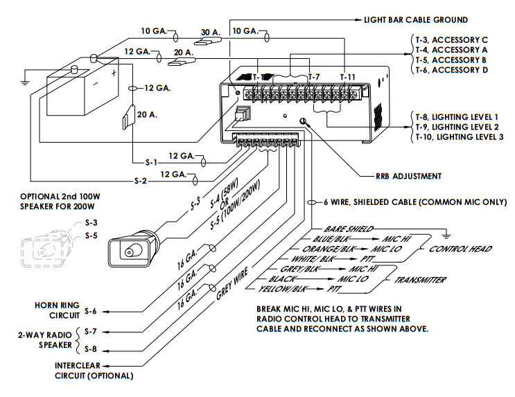
8 Position Terminal Block- ( see wiring diagram )
S1 – +12VDC, connect to a positive +12 volt DC source. It is recommended that the user protect this wire with a 20 Amp fuse or circuit breaker located at the source. Use #14 gauge wire.
S2 – GROUND, connect to the negative terminal of the battery. This supplies ground (earth) to the siren. Use #14 gauge wire.
S3 – Speaker Common, connect to one of the wires from speaker.
S4 – 58W Speaker, connect to the remaining speaker lead for 58W speaker only.
S5 – 100/200W Speaker, connect to the remaining speaker lead for 100/200W operation (1-100W, 11 ohm speaker or 2-100W, 11 ohm speakers connected in parallel).
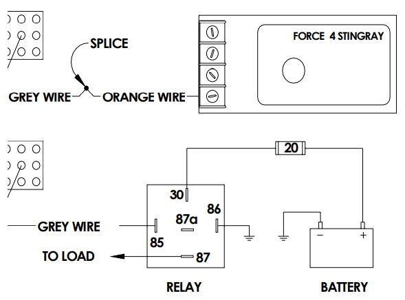
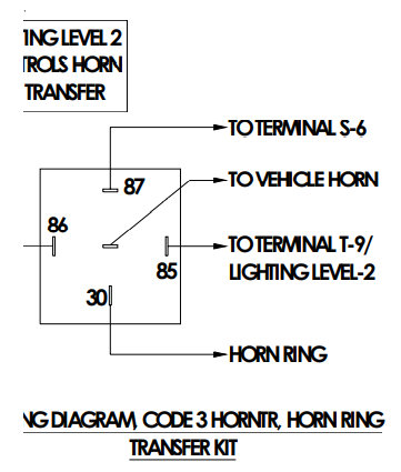
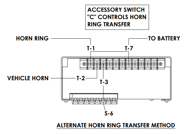
S6 – Remote input (Horn ring or foot switch) can be configured for either ground (earth) or positive signals. Unit is configured for a ground ( earth ) at the factory. See DETAIL A for further information on configuring for a +12V input.
S7 – RRB, connect to one side of the two-way radio speaker.
S8 – RRB, connect to the second side of the two-way radio speaker
Power Distribution Connections (“L4” Models)
A #8 stud is provided on the rear of the unit and is intended for use ONLY as a convenient ground (earth) ” tie-point ” for the light bar wiring. It is not an adequate ground (earth) for the siren or the light bar. It is recommended all ground (earth) wires attached here be terminated with a crimp-on ring terminal.
11-Position Terminal Block – Lighting Control – (See Wiring Diagram)
IMPORTANT! Remember auxiliary outputs A, B & D on L4 models can supply a maximum of 20 Amps each for a combined total of 30 Amps. Install appropriate fuses in each output wire as close to the siren as possible.
T1 – SW C COM – Common or power feed for Auxiliary Switch “C”. Terminals are a SPDT circuit that may be connected as a momentary (or latching depending on the switch ordered) ignition controlled circuit, or used for switching auxiliary circuits. It will Handle 10 Amps, and should be protected with a fuse at the battery if individually fed.
T2 – SW C NC – Connect to the load to be controlled by the normally-closed contact on Auxiliary Switch “C”.
T3 – SW C NO – Connect to the load to be controlled by the normally-open contact on Auxiliary Switch “C”.
T4 – AUXILIARY SW A, connect to the load to be controlled by Auxiliary Switch “A”.
T5 – AUXILIARY SW B – Connect to the load to be controlled by Auxiliary Switch “B”.
T6- AUXILIARY SW D – Connect to the load to be controlled by Auxiliary Switch “D”.
IMPORTANT! The total combined current for the auxiliary outputs A,B & D Must not exceed 30 Amps total.
T7 – +12VDC – Connect to the positive terminal of the battery with 30 Amp circuit protection. Locate the fuse or circuit breaker at the battery and use size 10 AWG wire minimum. This terminal powers switches A,B & D only.
T8 – LEVEL 1, connect to the first level of warning lights (Green LED) position “1” on level switch.
T9 – LEVEL 2, connect to the second level of warning lights (Yellow LED) position “2” on level switch.
T10 – LEVEL 3, connect to the third level of warning lights (Red LED) position “3” on level switch.
T11 – +12VDC – Connect to the positive terminal of the battery with 30 Amp circuit protection. Locate the fuse or circuit breaker at the battery and use size 10 AWG wire minimum. This terminal powers the 3-Level lighting control switch only.
NOTE: LEVEL 1, LEVEL 2, LEVEL 3, switch progressively. Switch position 1 provides +12 volts at terminal T8. Switch position 2 provides +12 volts at terminals T8 & T9. Switch position 3 provides +12 volts at terminals T8, T9 & T10.
Lighting Controls (For L4 Models Only)
WARNING LIGHTS 3-LEVEL PROGRESSIVE SLIDE SWITCH:
Position 1 – Supplies power to Lighting Level 1. Illuminates Green LED. Activates LightAlert if supplied
Position 2 – Supplies power to Lighting Levels 1 & 2. Illuminates Green and Yellow LED’s. Activates LightAlert and SirenLock options if supplied.
Position 3 – Supplies power to Lighting Levels 1,2, & 3. Illuminates Green, Yellow, AND Red LED’s.
Activates LightAlert and SirenLock if supplied.
Auxiliary Switches:
AUXILIARY SWITCH “A” – Supplies power to the load connected to terminal SW A.
AUXILIARY SWITCH “B” – Supplies power to the load connected to terminal SW B.
AUXILIARY SWITCH “C” – Operates circuit connected to terminals SWC NO, SWC NC, SWC COM.
Functions as a latching or momentary output, depending on the type of switch installed.
AUXILIARY SWITCH “D” – Supplies power to the load connected to terminal SW D.
SirenLock – The SirenLock option, when not defeated by means of the internal switches, allows siren tones (Wail, Yelp, and Hi-Lo) to be produced only when the Warning Light Switch is in the Lighting Level 2 (Green and Yellow LED’s) or Lighting Level 3 (Green, Yellow, and Red LED’s) position. Air Horn, Radio
Rebroadcast, and Public Address are unaffected by this option.
Options
LightAlert TM (L4 Models Only)- An audible alarm pulse that indicates that either the primary warning system or one of the auxiliary control circuits is on. User defeatable.
SirenLock TM (L4 and L6 Models Only)- An interlock circuit between the siren and the light control circuits that permits automatic siren tones only when the progressive switch is in Level 3 or in Level 2 or 3 (user selectable – works in conjunction with the horn transfer relay). This feature is used in jurisdictions that
require warning lights to be on before the siren is activated.
InterClear® This unique feature can be used to activate additional warning lights for 7 seconds when in an Hit-N-Go override or ” scrolling ” by pushing a single button or the vehicle horn ring, thus allowing an additional level of warning in situations such as intersections without the operator having to take his hands off the wheel or his eyes off the road.
Pluggable Microphone – A plug-in microphone jack in lieu of the standard wired-in microphone may be specified. A plug-in noise-canceling microphone must be ordered separately if needed.
Specifications
Siren Section
Input Voltage – 10 to 16 VDC, negative ground (earth).
(Note: Operation above 14 VDC for an extended period of time may result in speaker damage.)
Operating Current:
5 Amps @ 13.6V with 19-ohm load ( 58 W Spkr )
8 Amps @ 13.6V with 11-ohm load ( 1 – 100 W Spkr )
16Amps @ 13.6V with 5.5-ohm load ( 2 – 100 W Spkrs )
Standby Current: 18 mA excluding backlighting
Cycle Rate:
WAIL – 11 cycles/minute.
YELP – 200 cycles/minute.
Voltage Output ( approx. ) 64 V peak-to-peak
Audio Section
Audio Response:
3 dB down points – 500 to 3000 hz.
1000 hz. 0 dB Reference
Audio Distortion: 10% or less below clipping.
Lighting Section (“L4” Models Only)
Warning Light Control:
Progressive switching, 3 levels 30 Amps. maximum combined total for Levels 1,2 & 3
Level 1 30A maximum Green LED Indication
Level 2 30A maximum Yellow LED Indication
Level 3 30A maximum Red LED indication.
Auxiliary Controls A, B, C, D switches
A,B, C & D switches are latching, Push-on/off (standard), may be ordered as momentary Independent circuits
30 Amps. maximum combined total for switches A,B & D
20 Amps. maximum load for any single output A,B, C, or D
Audible alarm (optional)
Siren Tones
Code 3 V-Con Air Horn
Code 3 V-Con Manual Wail
Code 3 V-Con Wail
Code 3 V-Con Yelp
Code 3 V-Con Hyper Yelp
Manuals / Brochures
Code 3 V-Con & MasterCom Advertisement
Code 3 Installation & Operation Instructions V-Con Siren
Link
V-Con® – CODE 3 (code3esg.com)
Video
About The Author
Code 3 Garage
I started my career as a police officer in 1989 with the Geneva on The Lake Police Department. I worked part time as a police officer and full time as a Security Sergeant doing armed mobile security patrols for a local security company. In 1990 I became a State Trooper with the Ohio State Highway Patrol. During my career as a State Trooper I was certified as a Technical Crash Investigator, OPOTA Police Instructor, OPOTA Police Driving Instructor, LASER Instructor, and received awards for ACE (Auto Larceny) and Post Trooper of The Year. Code 3 Garage is a mix of my inner automotive gearhead, and public safety background. I hope you enjoy it!