What Is Radar:
The word “RADAR” is an acronym for RAdio Detection And Ranging. Police Radar is only one type of a small family of radar devices that provide no “range” information. This means that radar devices used by police do not provide the distance to the targeted vehicle. This also means that these radar devices do not fit the true definition of the acronym. However, the term radar is still used to describe these devices.
How Does Radar Work?
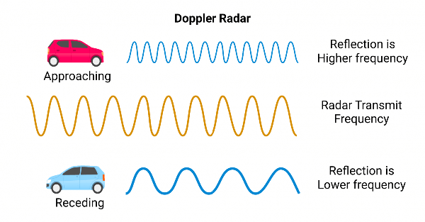
Radar works on the Doppler Principle. The Doppler Principle states:
When a signal is transmitted at a known frequency and reflected back from a moving vehicle it increases or decreases in frequency in direct proportion to the speed of the vehicle.
- If the vehicle is moving towards the Radar, the reflected signal will have a higher frequency than the transmitted signal.
- If the vehicle is moving away from the Radar, the reflected signal will have a lower frequency.
- If the Radar and a vehicle are both standing absolutely still, there is no relative motion; hence, the received signal will have the same frequency as the transmitted signal.
So basically, if you point the RADAR at a parked car, it’s not going to give you a reading.
The horn from a moving train is a good example of the Doppler effect. As the train approaches a stationary listener the frequency pitch of the train horn sounds higher than when the train is even with the listener. As the train passes and moves away from the listener the pitch decreases. Car horns exhibit the same phenomenon, as does all sound.
Radar Frequencies:
Presently all traffic Radar operates on four bands:
- “S” Band – The “S” Band transmits on a frequency of 2,455,000,000 Hz (2.455 Gigahertz).
- “X” Band – The “X” Band transmits on a frequency of 10,525,000,000 Hz. (10.525 Gigahertz).
- “K” Band – The “K” Band at 24,150,000,000 Hz. (24.150 Gigahertz)
- “S”-Band – The older “S”-Band radar is not utilized very much and has fallen out of favor as operating band for police radar. In fact, most microwave ovens in use today use this frequency to heat food in our homes.
It can be shown mathematically, that at a transmitted frequency of 10.525 Ghz.(“X”-Band), a Doppler frequency of 31.4 Hz. will be produced for each mile per hour of target ground speed.
For Example: 31.4 Hz. x 60 mph = 1884 Hz.
Knowing this relationship we are able, by means of modern electronic circuitry, to convert the Doppler frequency into a digital presentation of the target’s speed in miles per hour.
Example: Vehicle Approaching 60 M.P.H. Reflected Frequency 10,525,001,884 cycles per second.
Transmitted Frequency -10,525,000,000 cycles per second
Doppler Frequency -1,884 cycles per second In the X-Band radar, the Doppler shift occurs at the rate of 31.4 cycles per second for each mile per hour. The Doppler shift for K-Band is 72.023 cycles per second for each mile per hour.
For a source of radio waves manufacturers have selected a sophisticated solid state device called a Gun Oscillator which generates radio energy in the microwave region, specifically at frequency of 10.525 Ghz, (X-Band). This high frequency radio energy is focused into a narrow beam and directed at the target vehicle at the speed of light; the universal constant. A small portion of the beam is reflected back to the transmitter where a second solid state device called a mixer diode compares the frequency of the reflected beam to the transmitted frequency. The difference is our old friend the Doppler principle.
How The Radar Accounts For A Moving Patrol Car
When the Radar is in the ‘Moving’ mode, the Radar actually transmits two signals. One detects the patrol cars ground speed, and the other detects the speed of the vehicle approaching the Radar. The Radar then deducts the speed of the patrol car (or its own speed) from the speed of the other vehicle to calculate it’s actual speed.
Simplified:
When the Radar is on and returns a signal from a moving object, the Radar calculates how fast the other vehicle is moving based on the change in frequency that is bounced back (reflected) from the target vehicle. If the patrol car (Radar unit) is moving, the Radar unit transmit a second signal to measure its own ground speed and deducts that speed from the target vehicle speed to get an accurate reading.
Same Direction Radar:
Modern Radar units will measure the speed of a vehicle going the same direction as long as the target vehicle is traveling faster or slower than the patrol vehicle so there is a Doppler shift.
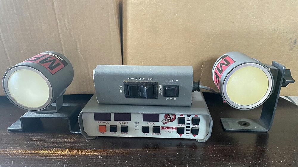
Radar Components:
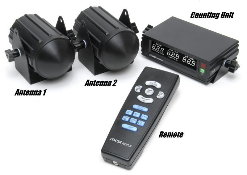
A Radar unit is made up of a Counting Unit (basically a computer that sends out the signal, reads the return signal, and then converts those frequency changes to a speed and display it), one or two antennas (the second antenna would mount in the rear window to ‘clock’ vehicles coming up behind the patrol vehicle when it’s stationary (stopped / parked) or clocking vehicles after they pass when moving), and a remote to activate the Radar signal.
Testing The Calibration:
Officers don’t calibrate their Radar, the check the calibration.
Lamp Segment Test (L/S): The lamp segment test illuminates all of the lamps and number segments verifying that they function. If any of the lamps or segments fail to illuminate the device should not be used and turned in for repair.
Internal Calibration Test (ICT): Internal Test: The internal calibration test will check the inner circuitry of the device and a preset number should be displayed in the readout window If this preset number is not displayed the device should not be used and turned in for repair. Refer to the manufacturers manual to determine which lamps and segments should illuminate and the preset number during the tests. Neither of these tests verify that the device is sending out a signal that is verified by the external test.
External Test: The external test checks the functions of the antenna and ensuring the counting unit is calculating correctly. The external test is done by using a tuning fork. The fork is designed to oscillate, or vibrate, at a known frequency that will result in the mph stamped on the fork. This represents the equivalent speed with relation to the Doppler shift. On the tuning fork certification of accuracy, the information given is the cycles per second of oscillation of each tuning fork, and its corresponding mile per hour. Each fork should be stamped with a serial number which also appears on the certification of accuracy.
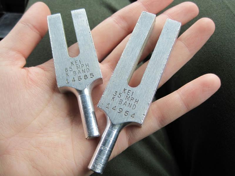
X-Band and K-Band forks are not interchangeable. Although two forks may each be marked with 35-mph, but the X-Band and K-Band operate at frequencies. At 35-mph an X-Band fork will not produce a 15-mph readout on a K-Band Radar instead of 35-mph.
Tuning Fork Tests and Tuning Fork Mode: A tuning fork test is the standard test for proving that the antenna and counting unit are functioning properly. In older analog radars, the dual tuning fork tests actually checked two different circuits, one each for patrol and target speeds. However, some newer Radars use a single circuit, the digital signal processor (DSP), to determine both speeds.
About The Author
Code 3 Garage
I started my career as a police officer in 1989 with the Geneva on The Lake Police Department. I worked part time as a police officer and full time as a Security Sergeant doing armed mobile security patrols for a local security company. In 1990 I became a State Trooper with the Ohio State Highway Patrol. During my career as a State Trooper I was certified as a Technical Crash Investigator, OPOTA Police Instructor, OPOTA Police Driving Instructor, LASER Instructor, and received awards for ACE (Auto Larceny) and Post Trooper of The Year. Code 3 Garage is a mix of my inner automotive gearhead, and public safety background. I hope you enjoy it!