What Is VASCAR:
VASCAR is a time-distance speed measurement device that is used by many State and local police agencies to enforce laws against speeding. VASCAR stands for Visual Average Speed Computer and Recorder (VASCAR). The instrument calculates an average speed using the basic formula given below:
Speed = Distance / Time
VASCAR allows an officer to “drive in” or “dial in” a distance. The officer then “times” the target vehicle with the instrument’s timing feature as the target vehicle covers the distance. VASCAR then uses these measurements to compute a speed in miles per hour (mph).
History:
VASCAR was invented by Arthur Marshall, a real-estate investor living in Richmond, Virginia in 1966. He was inspired to create the device after watching a police car driving dangerously trying to pace a speeder. The original version of the device was entirely mechanical, using a governed motor and a gear system to move a pointer to the correct speed value. Subsequent versions used a microprocessor to perform the speed calculations. By 1968, the device was in use in North Carolina, Indiana, Kentucky, and New York. In 1971, Marshall formed a company, Traffic Safety Systems, Inc., to market the device. After his death, Traffic Safety Systems was purchased by Power Systems & Controls, Inc., which had long manufactured the devices.
Mathematical Formula:
The mathematical formula used by VASCAR is a simple algebraic equation. Speed = Distance/Time = Miles/Hour
For the purposes of law enforcement officers, speed is normally expressed in terms of miles per hour. Distances and time, however, can be expressed in a number of different ways. For example, distances can be measured in miles, feet. or inches; and time can be measured in hours, minutes or seconds. When using VASCAR, a police officer will normally measure distance in feet and time by the second. Therefore, some elementary conversions are necessary for the basic speed formula.
Keep in mind that 1 Hour = 60 Minutes = 3600 Seconds
Also, 1 Mile = 5280 Feet
VASCAR measures the average speed of the target vehicle. By definition, average speed cannot exceed peak speed and is generally lower.
VASCAR Components:
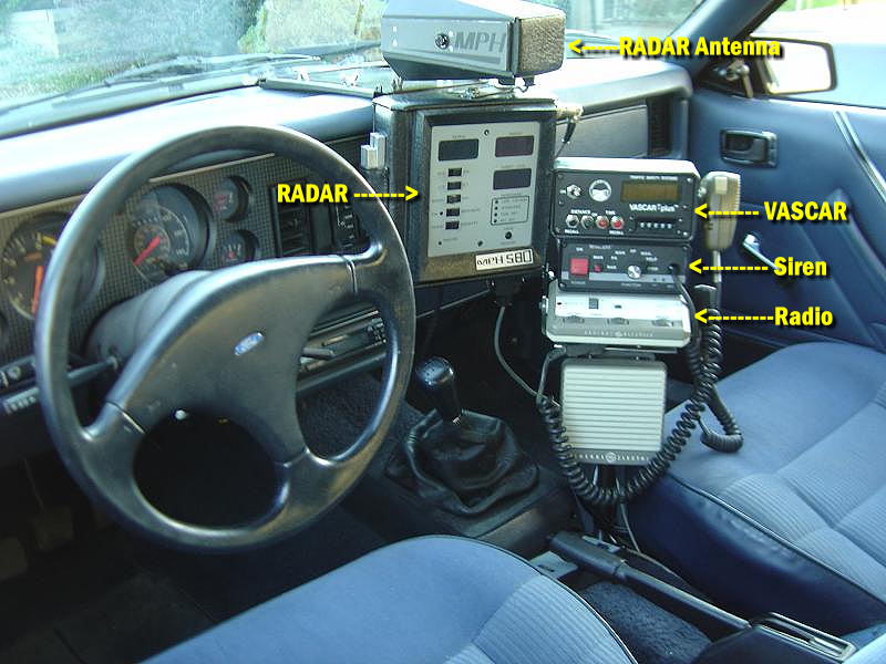
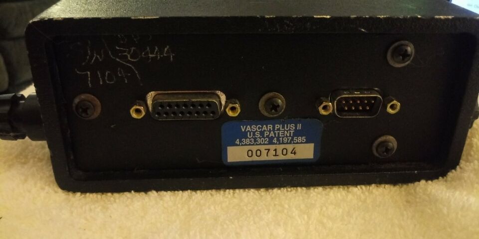
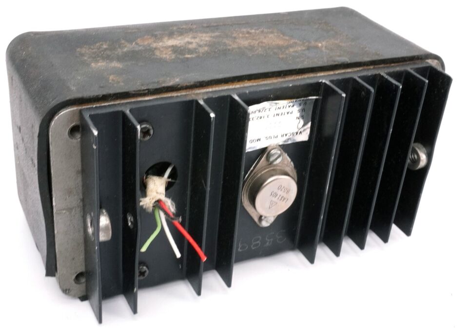
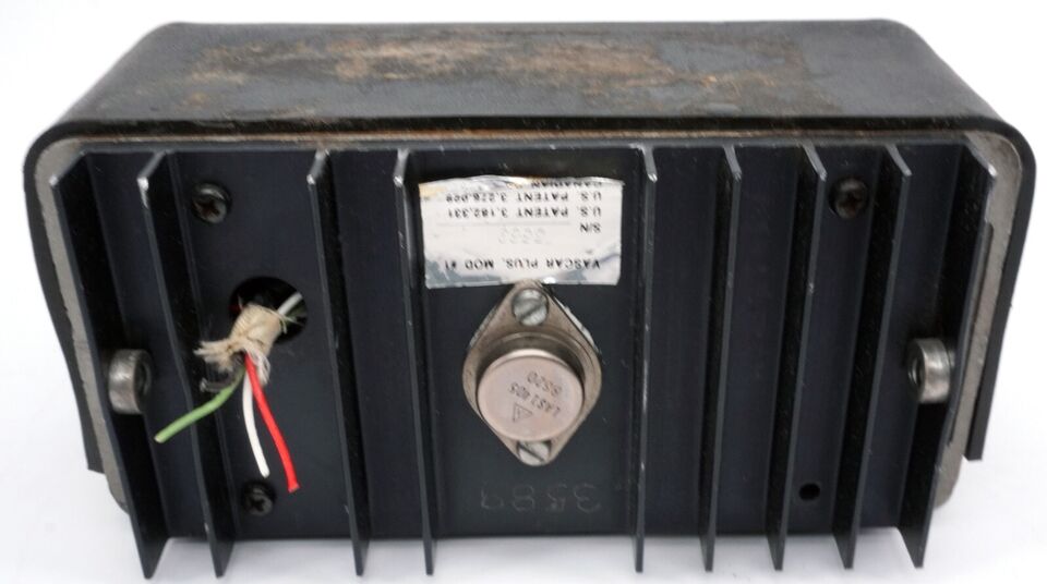
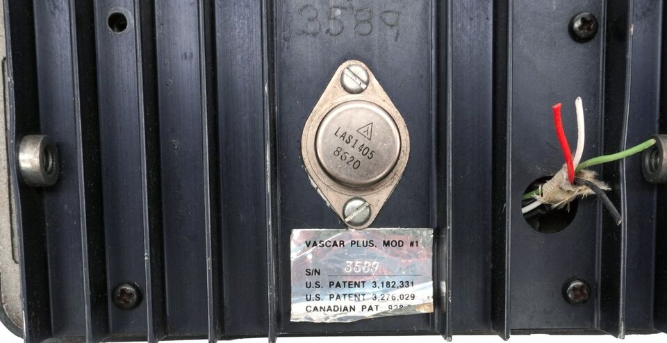
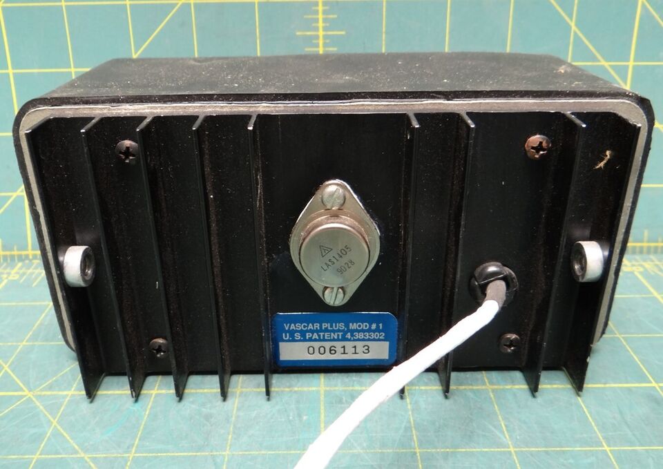
A complete VASCAR unit consists of two main parts: the control head and the odometer module.
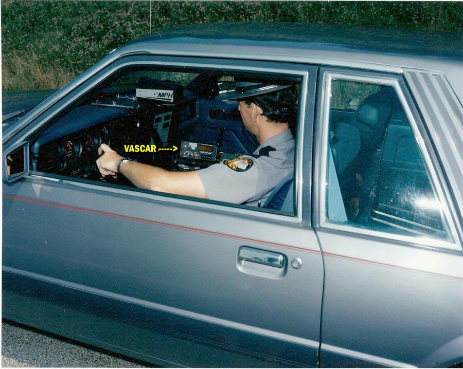
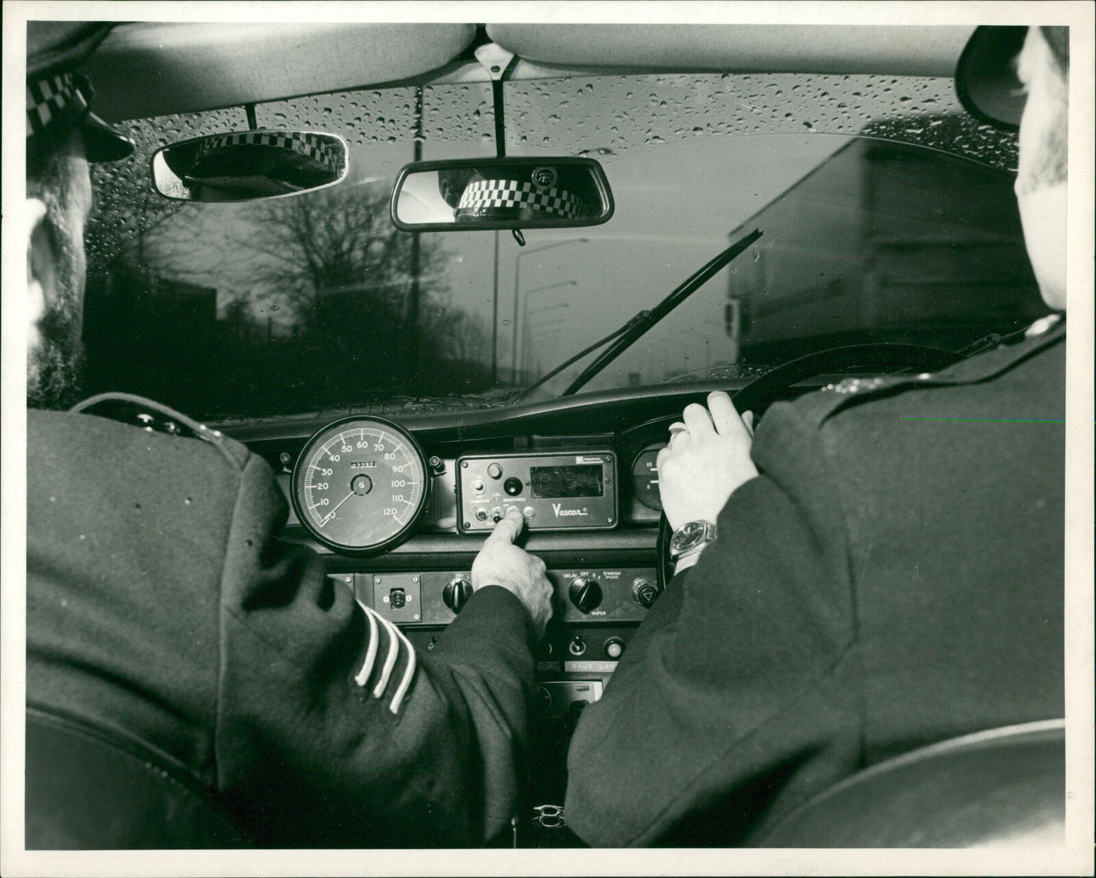
The control head is normally mounted inside the patrol car (or aircraft) and is in easy reach of the police officer who operates the vehicle. Many police departments mount the control head on an equipment rack between the two front seats or on the dashboard area. Regardless of the mounting location, the individual controls should be easily within reach of the police officer who should also have a clear view of the digital display on the control head.
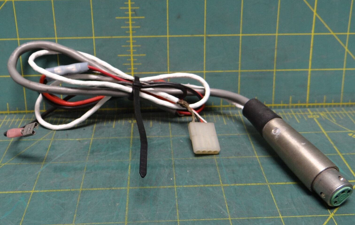
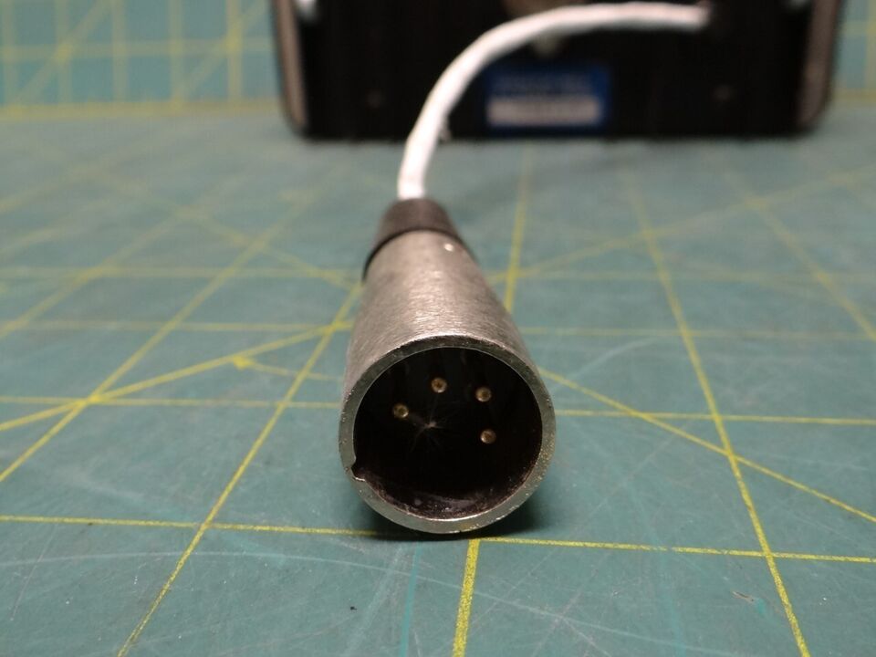
The odometer module is a transducer that sends magnetic pulses to the computer in relation to distance travelled by the patrol car. The module is connected to the transmission of the automobile by the odometer module cable. The accuracy of the odometer module, and the VASCAR unit itself, is independent of the accuracy of the speedometer.
The odometer module sends ten magnetic pulses to the computer for each turn of the odometer module cable. The transmission of the average automobile will turn the odometer module cable approximately 1000 times in a mile. One thousand turns of the cable, times ten pulses per turn, equals ten thousand pulses per mile travelled.
Bach pulse is equal to l / l0,000th of a mile. This relationship can also be used to calculate the theoretical distance travelled, or inches measured, in each “pulse”:
5280 x 12 /10,000 = 6.3 inches
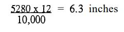
Therefore, the VASCAR unit measures distance in 6.3-inch increments.
A typical automobile odometer module cable turns 1,000 times in a mile and the odometer module creates 10 pulses per turn. Therefore, in theory, 10,000 pulses are generated per mile travelled. In reality, however, not every odometer module cable turns at 1,000 times per mile. Because of this, the VASCAR device must be calibrated to read the correct distance, or in other words, count the number of pulses in a mile.
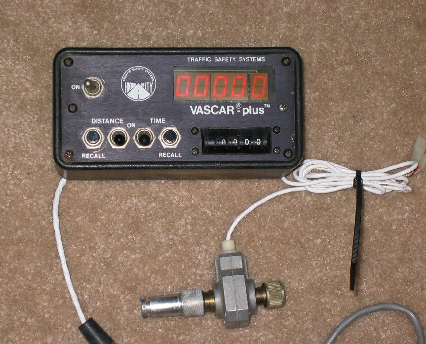
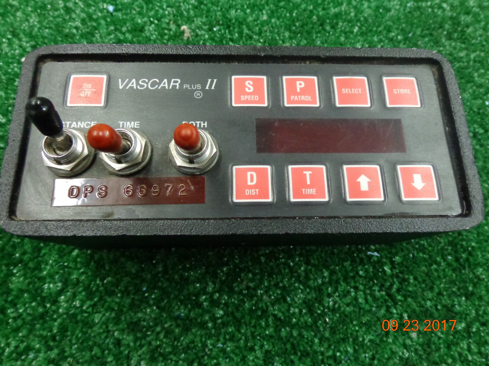
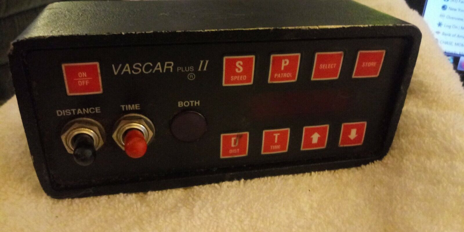
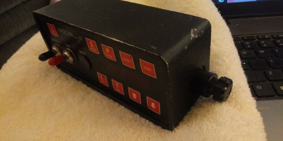
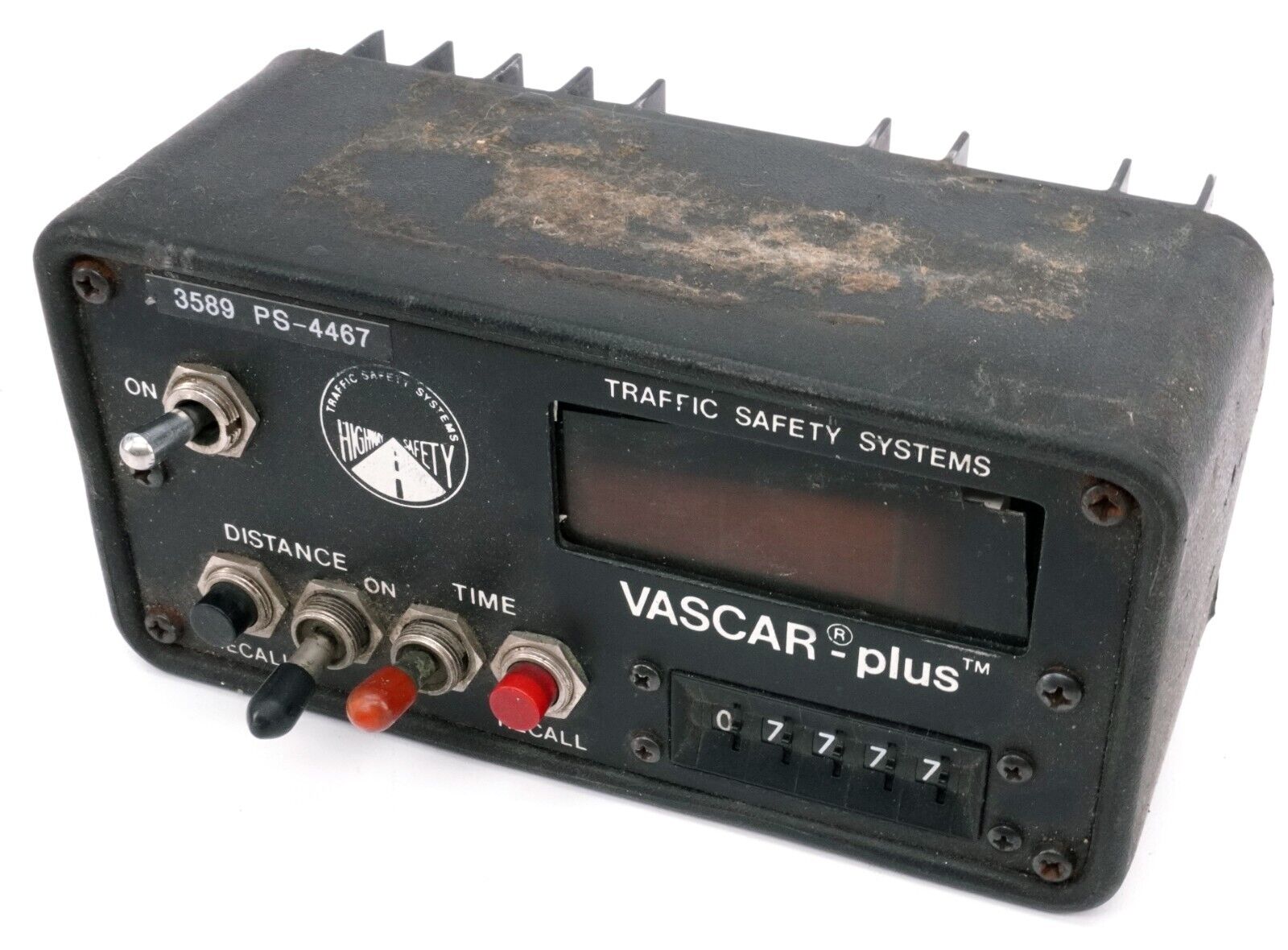
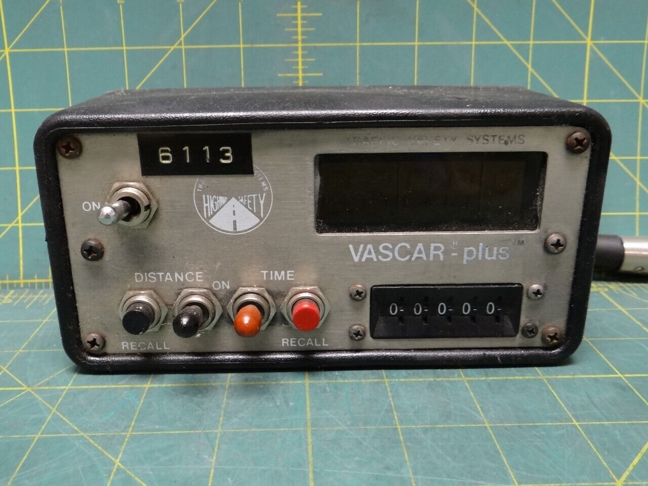
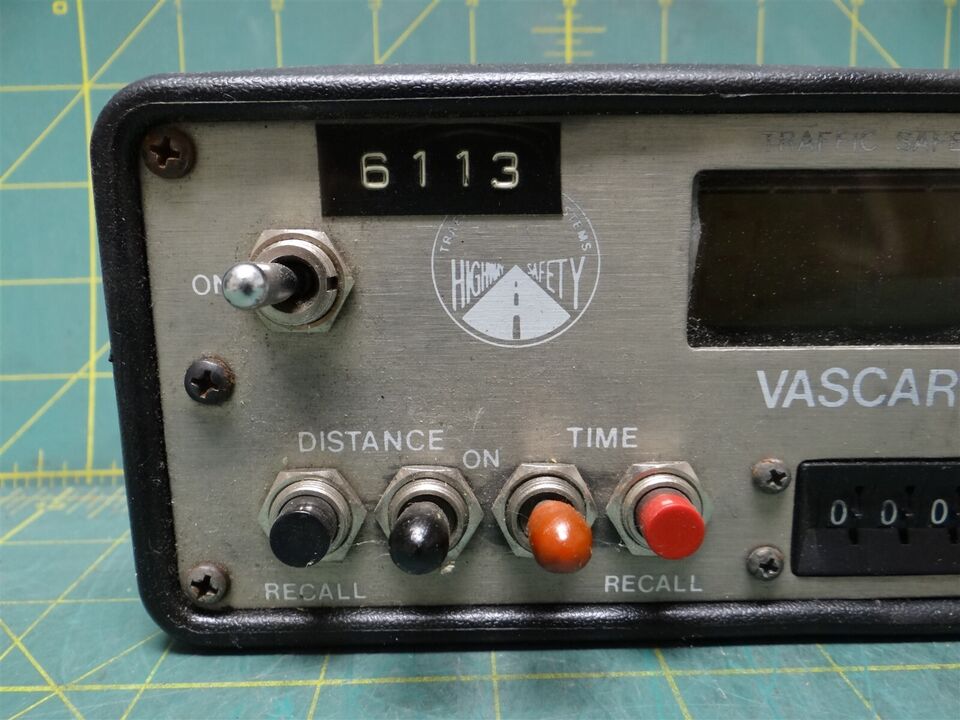
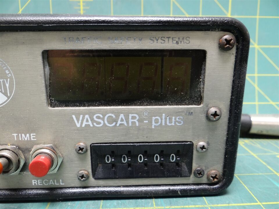
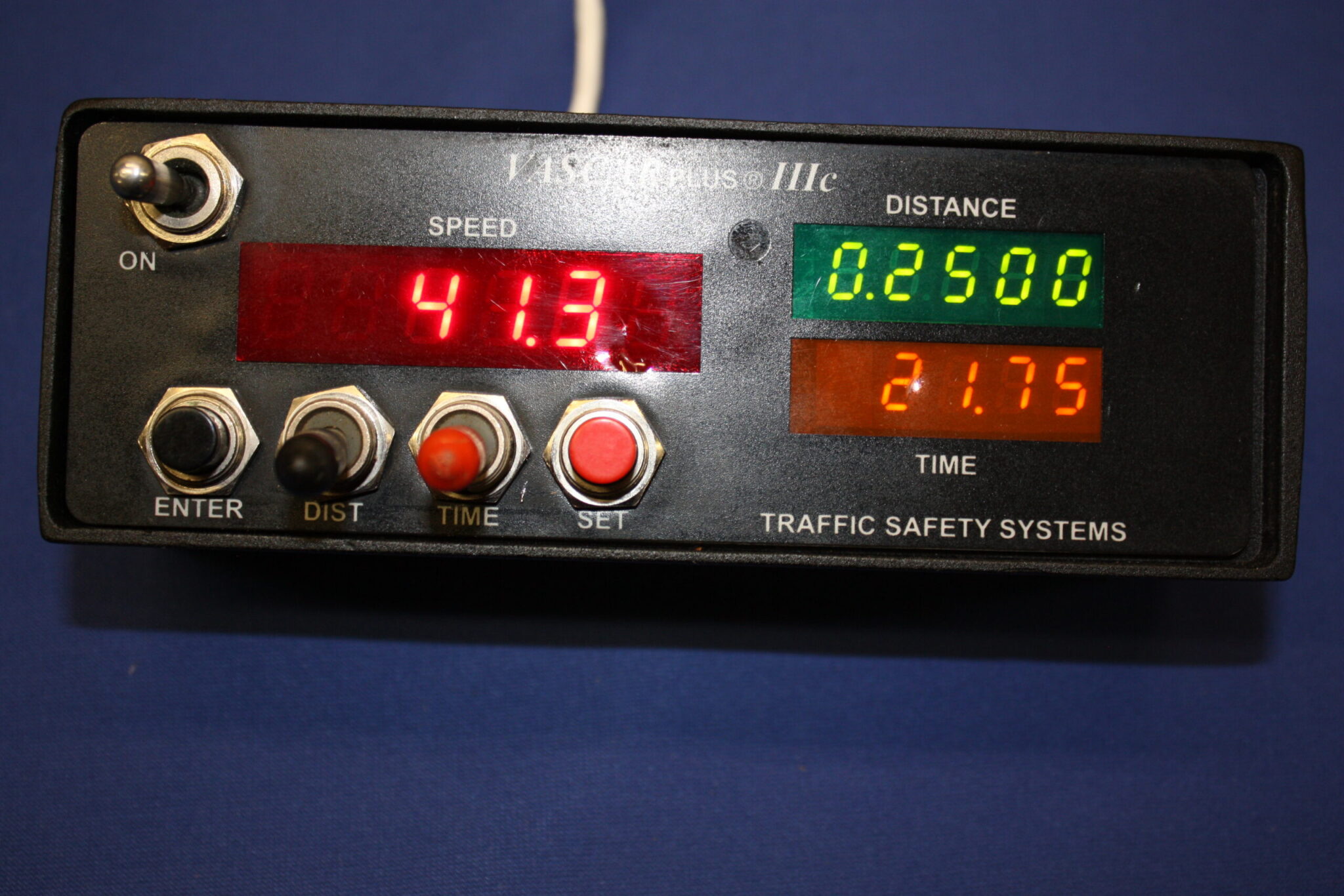
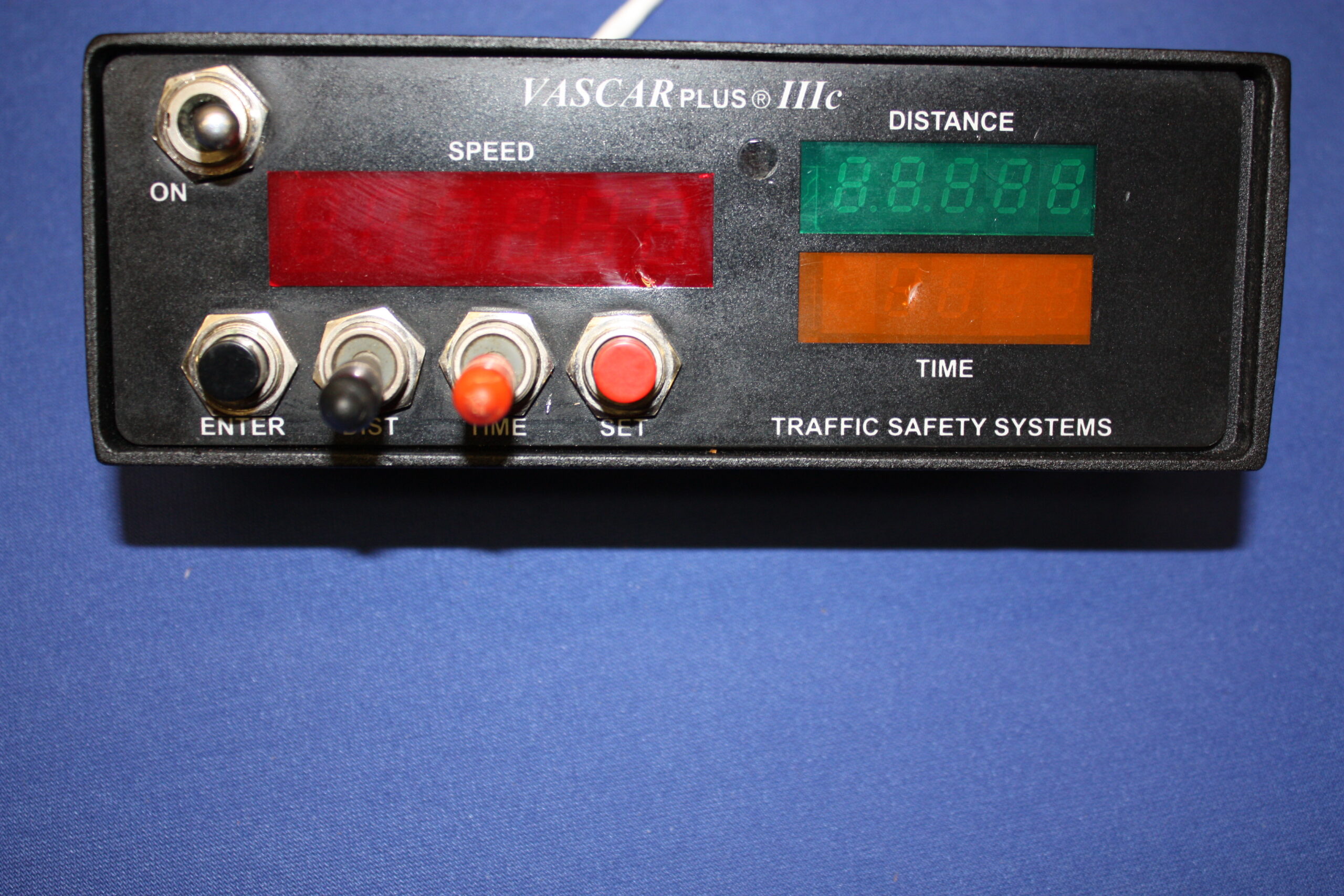
Bach VASCAR control head measures approximately 4 x 4 x 7 inches. The face of the head contains the following switches and/or features: an on-off toggle switch, an LED display, a red time toggle switch, a black distance toggle switch, a red time recall button, a black distance recall button and five thumbwheel switches.
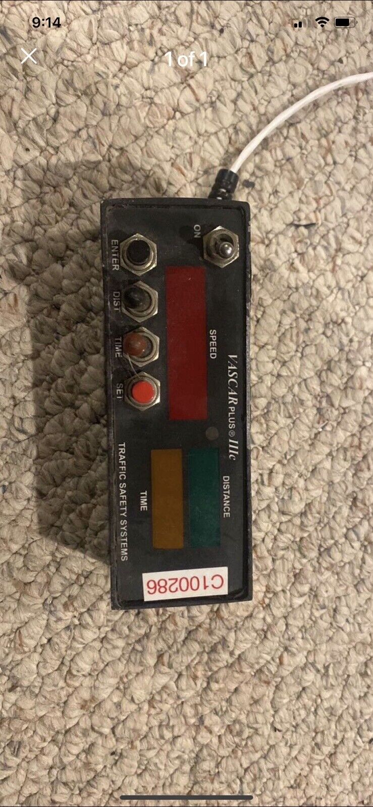
Control Head:
The control head contains the VASCAR computer as well as all operational switches, buttons and the LED readout. The face of the control head contains the following components:
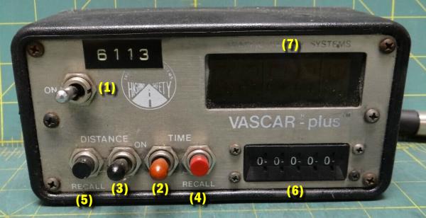
1. On/Off toggle switch for power
2. RED time switch
3. BLACK distance switch
4. RED time recall button
5. BLACK distance recall button
6. 5 thumbwheels
7. LED (readout) display
Theory Of Operation:
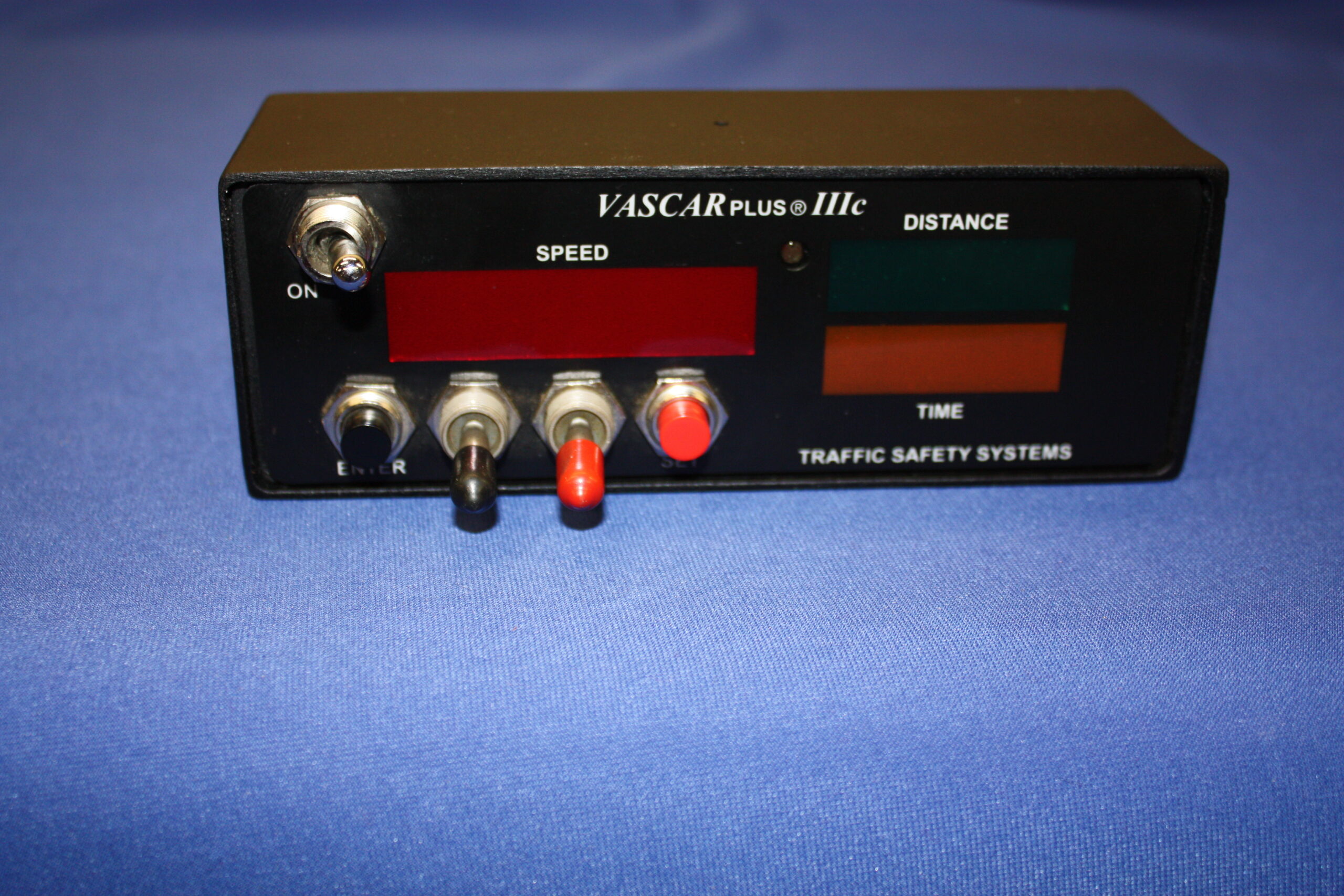
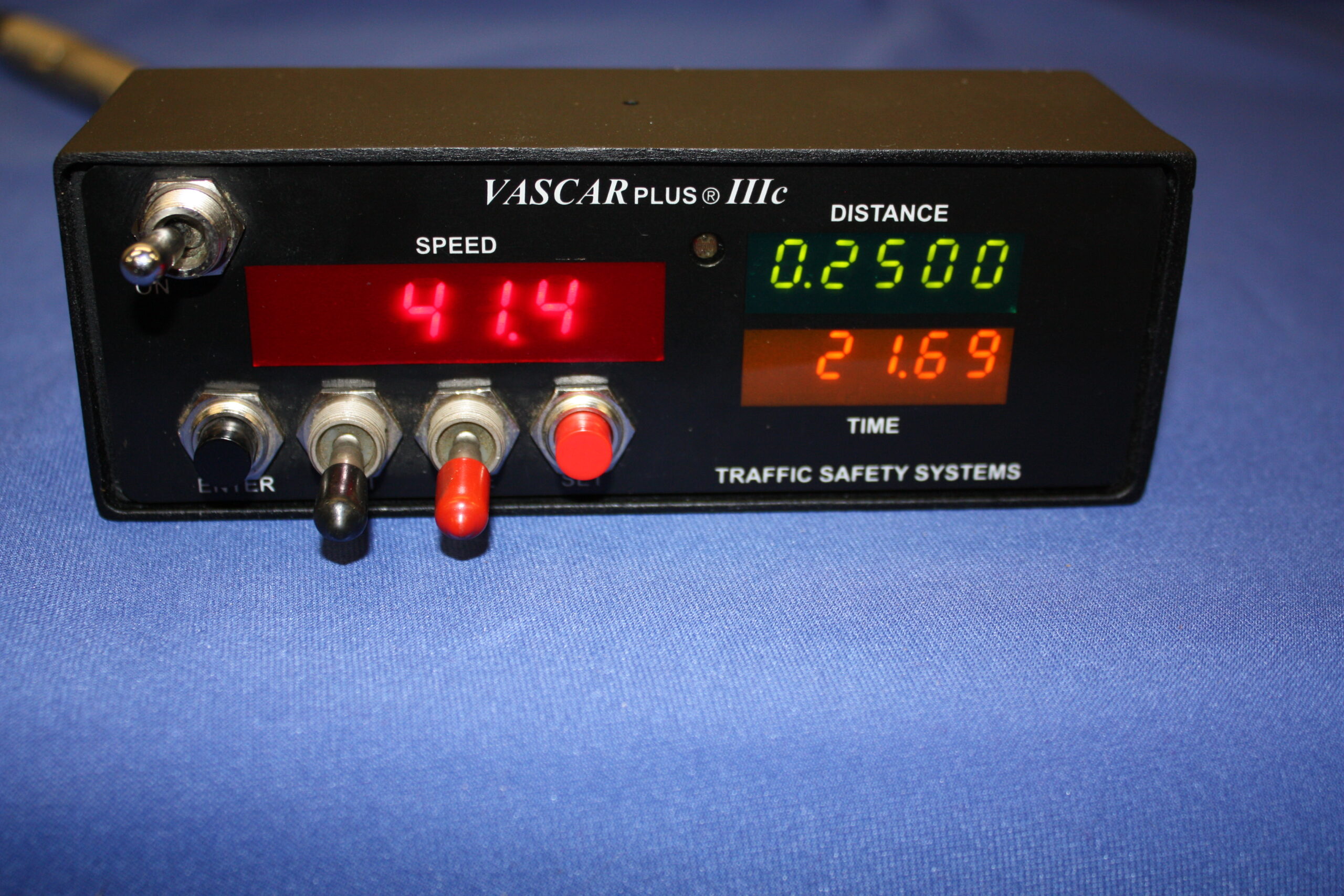
The control head also contains a computer that calculates the speed in miles per hour by dividing the distance the target vehicle travels by the measured time it takes to travel that distance. The miles per hour reading will be displayed in one-tenth mph increments. For example, 65.7 mph, 72.5 mph, etc. will be displayed on the LED readout.
“Time” is determined by the police officer by activating the red time switch as the target vehicle traverses the distance from point A to point B.
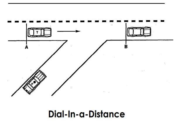
“Distance” is either “dialed in” or “driven in” by the police officer.
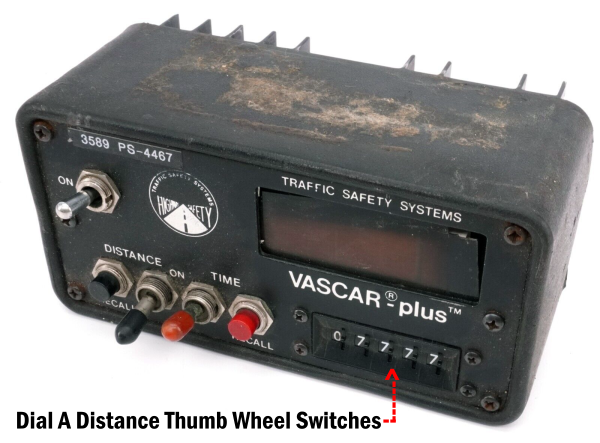
A. Dialing in Distance: A premeasured distance can be dialed into the VASCAR unit by using the five thumbwheel switches on the control head. The operator must first dial up a “9” on the far left thumbwheel. This first digit serves as an entry number. The operator then dials in the remaining digits which correspond to a decimal representation of a mile. For example:
Officer X plans to clock cars over a known distance of one-eighth (l/8) mile. One-eighth mile is equivalent to 0.1250 mile when expressed in decimal form (1 divided by 8 = .0.1250). To “dial in” this distance he would set up the thumbwheel display as follows: 9-1-2-5-0
Officer X would then depress the distance button and release it. Then the operator turns the left most dial from 9 to 0 . The course distance of l/8 mile is now registered in the computer, The distance that has been entered into the computer can now be verified by depressing the Distance Recall Button (LED should read 0.1250). Officer X is ready to time target vehicles by turning “on” the time switch when the target vehicle crosses the first reference point and turning “off” the time switch when the target vehicle crosses the second reference point.
Other examples of premeasured distances that can be entered in “dial a distance” are:
l/4 mile – (9)2500
l/3 mile – (9)3333
l/2 mile – (9)5000
Other distances can be entered, as well. For example, an officer on patrol may frequently use a premeasured course of 400 feet to clock vehicles. To enter this distance into the VASCAR unit he would first have to convert it to a decimal portion of a mile. In other words, he would have to divide the distance in feet by 5280 (the number of feet in a mile).
400 feet / 5280 = 0.0757 feet
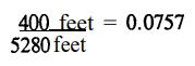
The officer would then “dial in” (9)-O-7-5-7 and press the black distance recall button to enter the distance. REMEMBER also to remove the “9” from the first (far left) thumbwheel before beginning clocks. Vehicles can now be clocked over this 400ft course.
IMPORTANT: Even though a distance. has been “dialed in” to the VASCAR unit, an officer can still clock a vehicle in the “moving mode” (measuring both time and distance). If neither the power nor the distance switch have been toggled during Dial-a-Distance, the original calibration number is still active in the computer, thus allowing immediate pursuit and use of VASCAR in the moving mode.
B. Driving in a Distance: (or Distance Measured with the Patrol Car). In this method the officer would measure the distance between two reference points by driving from point A to point B. Refer to Chapter 3 for a complete description of the procedure used to measure distance with the patrol vehicle. This distance is automatically recorded into the VASCAR computer and serves as the distance measurement in the basic speed equation.
Distances can be “driven in” in two basic ways. First, the officer can use VASCAR to measure the distance between two reference points (Chapter 3) and then position his patrol vehicle where he can observe target vehicles passing between the reference points. Since the distance input will have been recorded as the police officer “drove in” the distance, all that would be needed at this point would be a time measurement between the two reference points. The VASCAR operator would then use the time switch to obtain the speed measurement of the target vehicles.
The second method of “driving in” the distance would be used during the moving mode of clocking vehicles. In this case the patrol car is moving as the VASCAR operator clocks the target vehicle. The time is measured as the target V&L& passes from point A to point B and am is “m” as the patrol vehicle passes the same reference points. The activation of the time and distance switches are independent of each other.
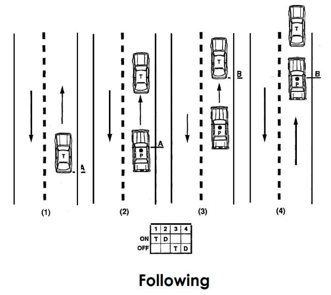
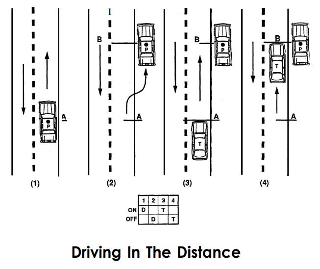
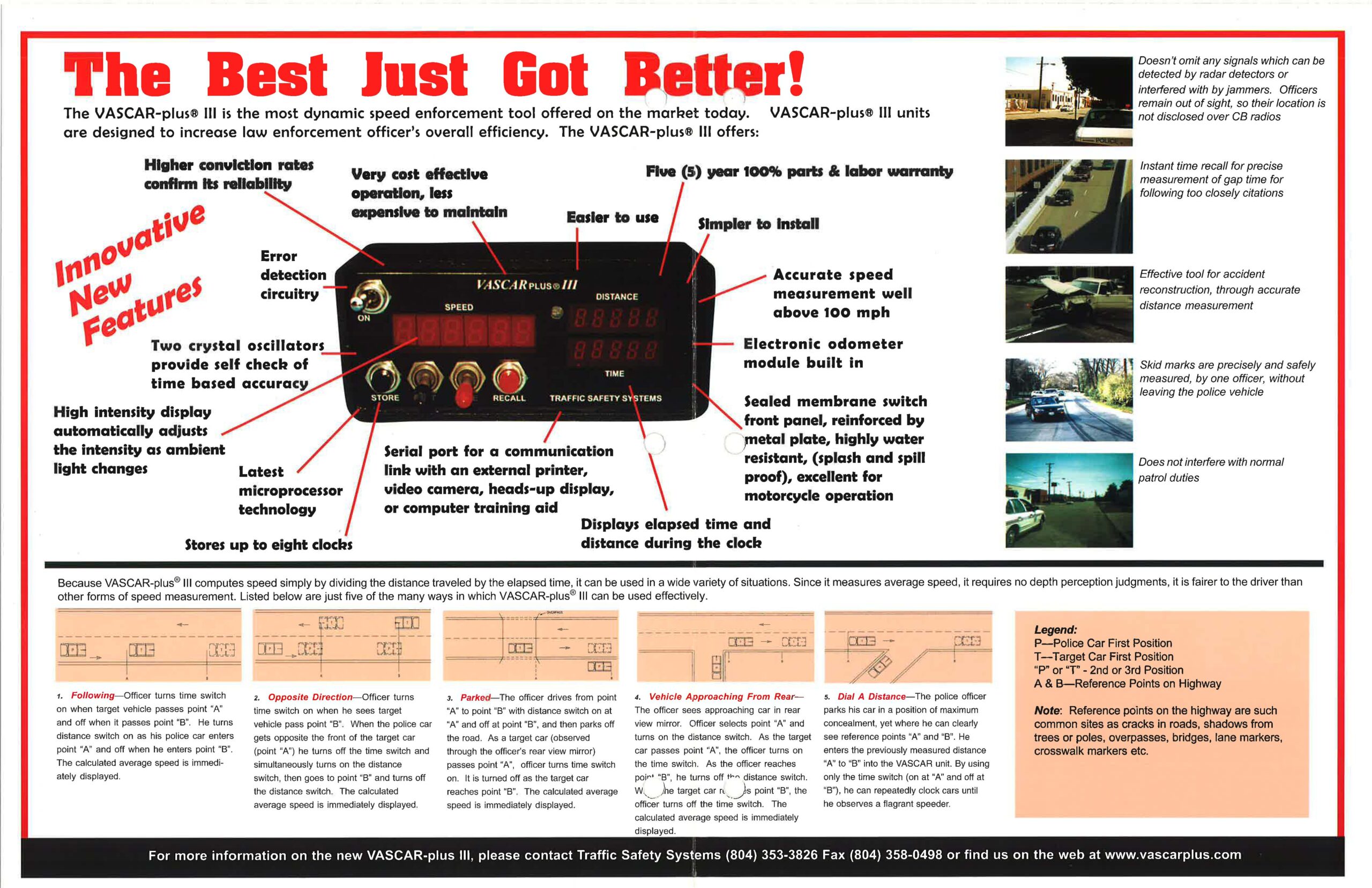
Basic Clocking Methods:
Legend:
- P – Police car
- T – Target car
- “A” and “B” – reference points on the highway
Following: Officer turns time switch “ON” when-target vehicle passes reference point “A” and turns distance switch “ON” when his police vehicle passes reference point “A.” Officer turns “OFF” time switch when target vehicle passes reference point “B” and turns “OFF” distance switch when his police vehicle passes reference point “B. ” (NOTE: The distance between the two vehicles need not be maintained. The speed of the two vehicles need not be the same.)
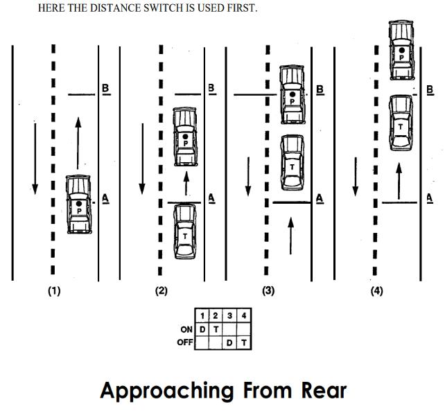
Target Vehicle Approaching From The Rear:
- A. Officer turns “ON” distance switch when the police vehicle passes reference point “A.”
- B. Officer turns “ON” time switch as target vehicle seen through the rearview mirror passes reference point “A.”
- C. Officer turns “OFF” distance switch when police vehicle passes reference point “B.”
- D. Officer turns “OFF” time switch as target vehicle seen through the rearview mirror passes reference point “B.”
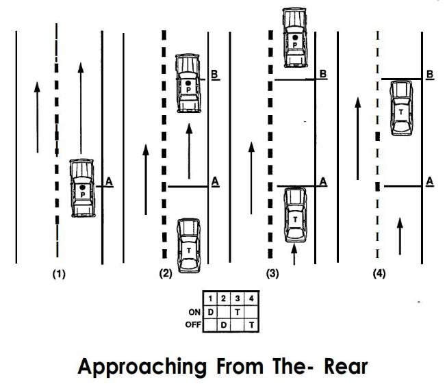
Target Vehicle Approaching From The Rear (Continued):
- A. Officer turns “ON” the distance switch at point “A.”
- B. Officer turns “OFF” the distance switch at point “B.”
- C. Using the rear-view mirror, the time switch is turned “ON” when the target vehicle reaches point “A.”
- D. The time switch is turned “OFF” when the target vehicle reaches point “B.”
You will note here the distance was measured first and then the time computation.
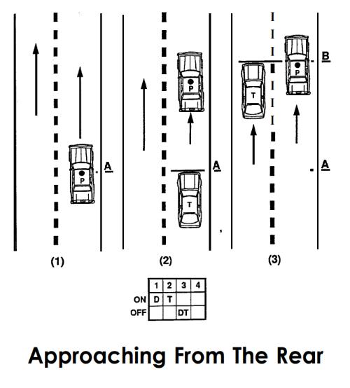
Target Vehicle Approaching From The Rear: Utilizing the rear-view mirror, using one road location point, and using the target vehicle as the second point as the target vehicle passes the clocking vehicle. This method is started in the same way as in (Figure 4) but is completed differently.
- A. When the clocking vehicle reaches a location point “A” the distance switch is turned “ON.”
- B. Using the rear-view mirror, the time switch is turned “ON” when the target vehicle reaches the same point.
- C. The target vehicle continues to overtake until it gets alongside the clocking vehicle. At this point both the time and distance switches are turned “OFF” simultaneously.
Stationary Mode – Driving In The Distance: The police officer drives from reference point “A” to reference point “B” with the distance switch “ON” at reference point “A” and “OFF” at reference point “B” and parks off the road. When the target vehicle, as seen through the rearview mirror passes reference point “A” the officer turns “ON” the time switch and when vehicle passes reference point “B” he/she turns the time switch “OFF.”
NOTE: Reference point “B” will always be the police vehicle.
Stationary Mode – Dial In A Distance: The police officer parks the police vehicle in a position from which the reference points, “A” and “B” can be clearly seen. Having previously measured the distance between reference points “A” and “B”, the officer now dials in the distance on the thumbwheel switch. By use of the time switch only (“ON” at “A” and “OFF” at “B”) the officer can repeatedly check speeds until a violation is observed.
Calibration Of The Unit:
Establish a calibration course on a flat roadway with low traffic volume. The suggested minimum length is l/4 mile; however, a longer calibration course length may be established if desired or required by statute or departmental policy. You must be able to verify the length either because you personally measured the course, or it was measured by a qualified surveyor. In either case it is recommended that a steel measuring tape be used in the measurement of the calibration course. After measuring, the course must be marked in a permanent manner to enable the operator to return to the pre-measured course as needed.
Suggested methods of marking are with paint, surveying spikes, or concrete nails.
It is recommended that the operator select a point on the patrol vehicle to align with the marks at the beginning and end of the calibration course to ensure a high degree of accuracy. Examples of such marks might be body molding screws, manufacturer door jamb emblems, body seams or door edges.
Calibration Steps:
- a. Turn power switch to the “OFF” position
- b. Set all thumbwheel switches to ”0” position
- c. Tum power switch to the “ON” position, LED’s should indicate all 8’s.
- d. Set thumbwheel switches to the calibration course length:
- l/4 mile = 02500
- l/3 mile = 03333
- l/2 mile = 05000
- e. At the start of the calibration course, the operator should place the reference point of the patrol vehicle on the mark at the beginning of the calibration course and place the distance switch (black) UP. Drive to the end of the calibration course smoothly and in as straight a line as possible. After positioning the reference point on the patrol vehicle on the mark at the end of the calibration course, place the distance switch (black) DOWN.
- f. The number that appears on the display is the calibration number (e.g., 09987).
- g. Enter the Calibration Number into the thumbwheels, from left to right. Turn the power switch to the “OFF” position, then to the “ON” position. The LED display will indicate all 0’s. The unit is now calibrated. It is recommended that the calibration number be recorded for possible future reference (e.g., court notes, calibration log, etc.).
VASCAR Wiring Diagrams:
GM with Electronic Speedometer PLUS III
GM with Electronic Speedometer PLUS II
Ford Explorer with Electronic Speedometer PLUS III
Ford Explorer Electronic Speedometer
Videos:
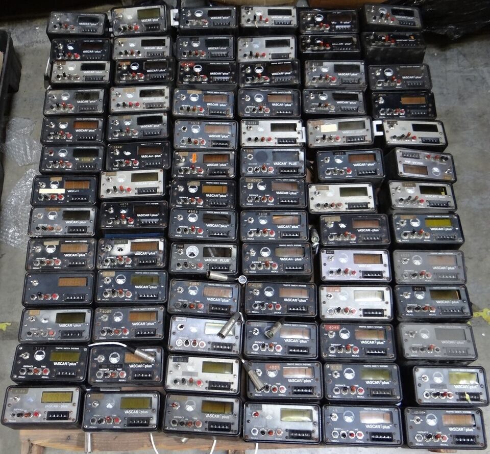
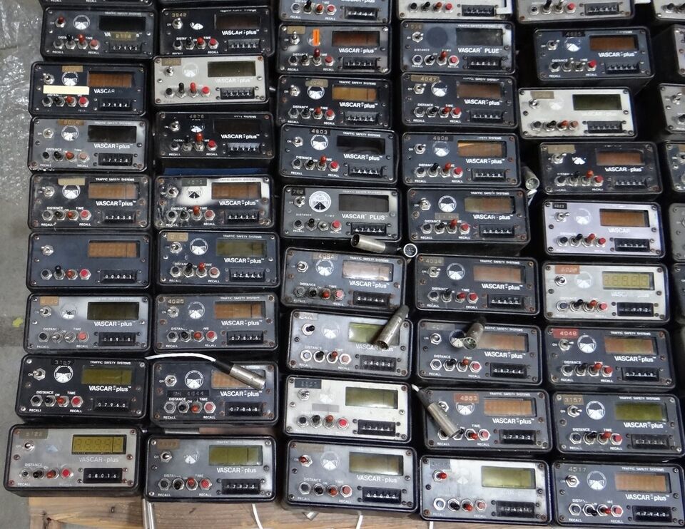
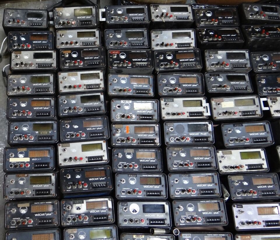
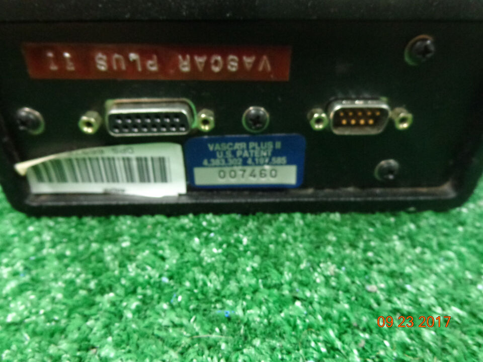
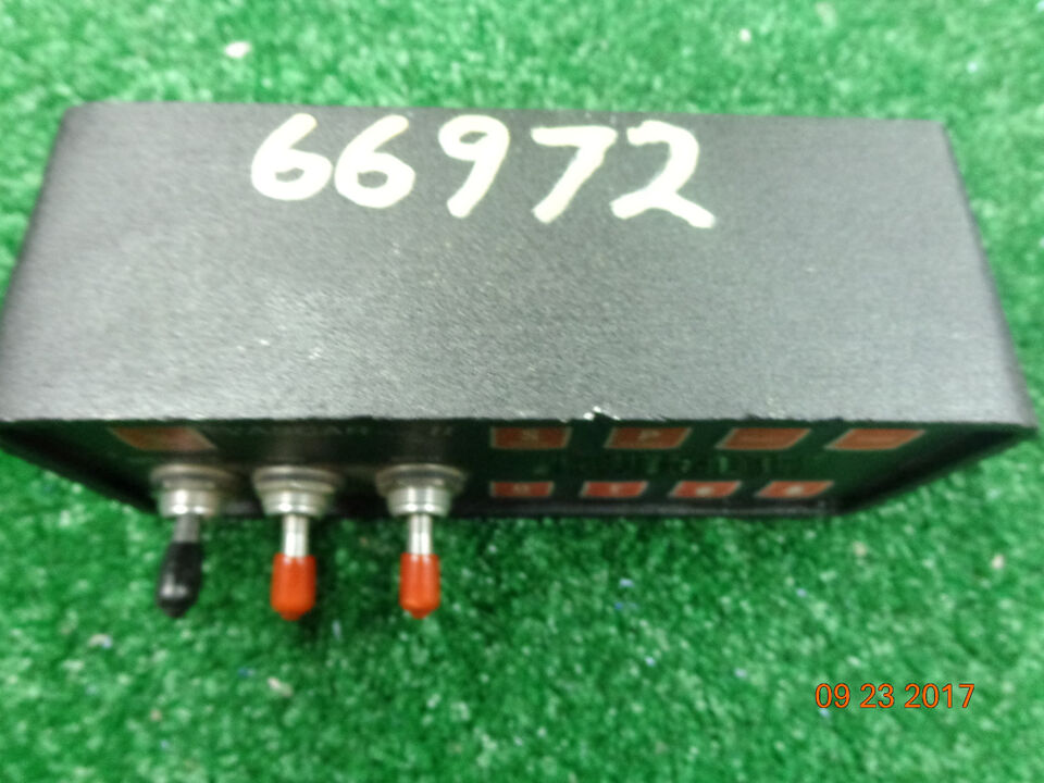
Photos:
Click the photos to enlarge.


About The Author
Code 3 Garage
I started my career as a police officer in 1989 with the Geneva on The Lake Police Department. I worked part time as a police officer and full time as a Security Sergeant doing armed mobile security patrols for a local security company. In 1990 I became a State Trooper with the Ohio State Highway Patrol. During my career as a State Trooper I was certified as a Technical Crash Investigator, OPOTA Police Instructor, OPOTA Police Driving Instructor, LASER Instructor, and received awards for ACE (Auto Larceny) and Post Trooper of The Year. Code 3 Garage is a mix of my inner automotive gearhead, and public safety background. I hope you enjoy it!